WM-EX527
6
• This set can be disassembled in the order shown below.
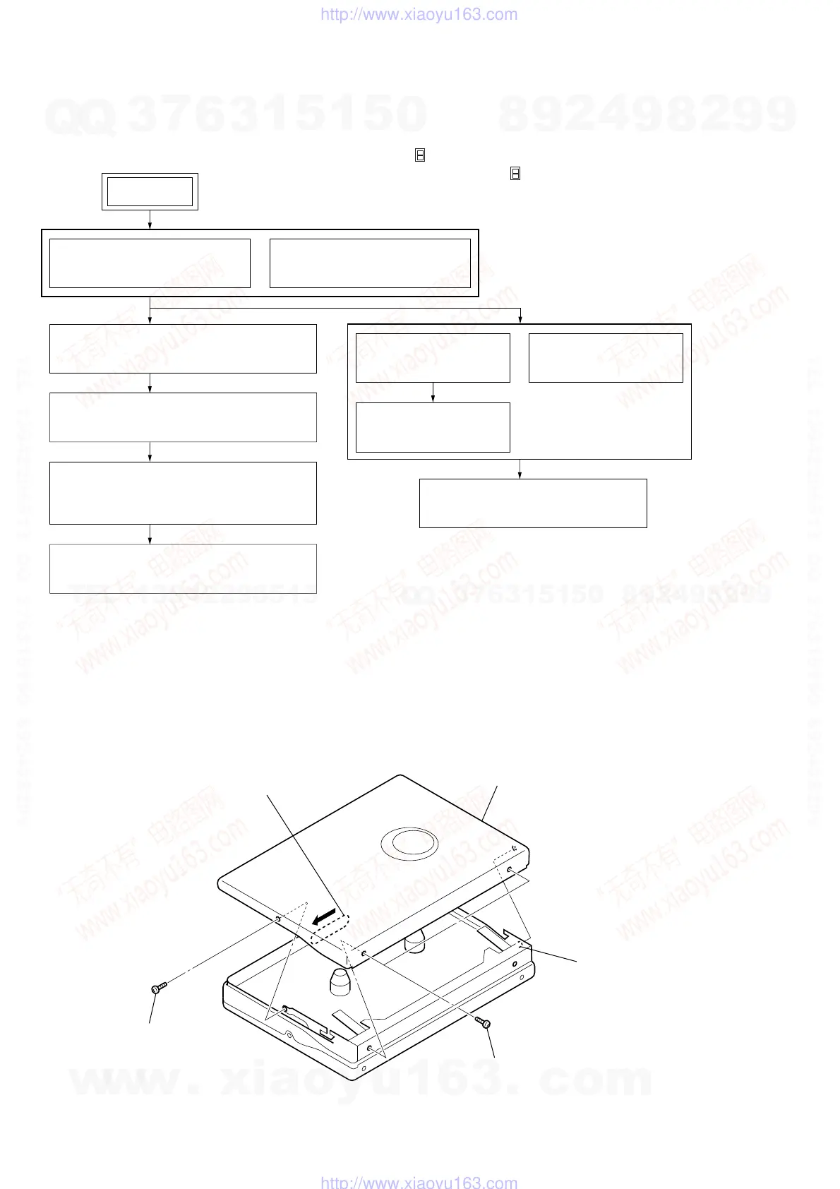
3-1. DISASSEMBLY FLOW
SECTION 3
DISASSEMBLY
Note: Follow the disassembly procedure in the numerical order given.
3-2. CASSETTE LID ASSY
3-4. REEL ORNAMENT BLOCK ASSY
(Page 7)
3-2. CASSETTE LID ASSY
(Page 6)
3-3. CASE BLOCK ASSY
(Page 7)
3-9. HOLDER (FS) SECTION
(Page 10)
3-10. PINCH LEVER (N) ASSY,
PINCH LEVER (R) ASSY
(Page 11)
3-11. MAGNETIC HEAD (PLAYBACK) (HP901)
(Page 11)
3-8. MOTOR (CAPSTAN/REEL) (M901)
(Page 10)
3-5. BATTERY HOLDER
(Page 8)
3-7. MAIN BOARD
(Page 9)
3-6. BELT (F2)
(Page 8)
Note 1: The process described in can be performed in any order.
Note 2: Without completing the process described in , the next process can not be performed.
SET
4
cassette lid assy
2
two screws
(M1.4)
2
screw
(M1.4)
1
Open the cassette lid assy.
3
boss
w
w
w
.
x
i
a
o
y
u
1
6
3
.
c
o
m
Q
Q
3
7
6
3
1
5
1
5
0
9
9
2
8
9
4
2
9
8
T
E
L
1
3
9
4
2
2
9
6
5
1
3
9
9
2
8
9
4
2
9
8
0
5
1
5
1
3
6
7
3
Q
Q
TEL 13942296513 QQ 376315150 892498299
TEL 13942296513 QQ 376315150 892498299
http://www.xiaoyu163.com
http://www.xiaoyu163.com
 Loading...