– 55 –
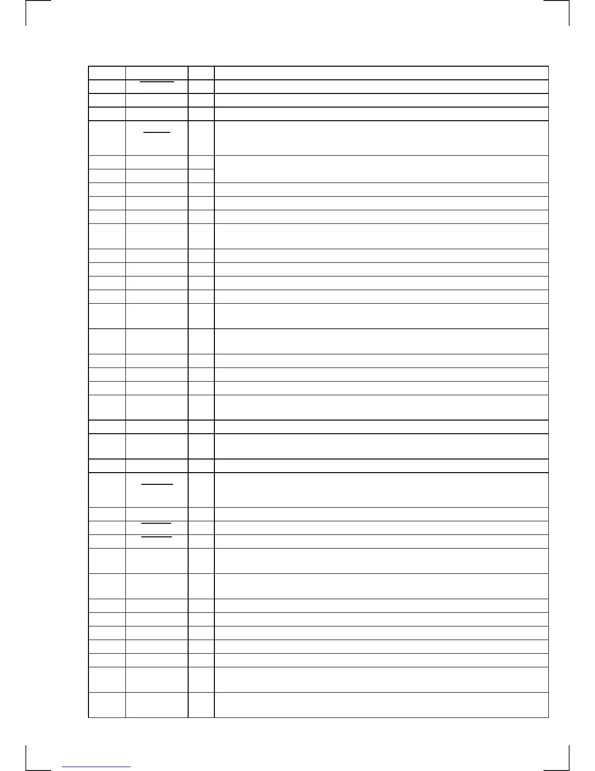
Pin No. Pin Name I/O Function
32 LCD INH O
Blank indicate control signal output to the liquid crystal display driver (IC900) “L”: no display
33
VSS
—
Ground terminal
34 C —
Connected to coupling capacitor for the power supply
35 AD-ON
O
A/D converter power control signal output terminal
When the KEYACK (pin &§) that controls reference voltage power for key A/D conversion input
is active, “L” is output from this terminal to enable the input
36 RE-IN0
I
37 RE-IN1
I
38 DVCC —
Power supply terminal (+5V) (for D/A converter)
39 DVSS —
Ground terminal (for D/A converter)
40 — I
Not used (fixed at “L”)
41 LCDANG
O
View field angle control signal is output when front panel is fully opened
“H”: front panel is fully opened
42 AVCC —
Power supply terminal (+5V) (for A/D converter)
43 AVRH
I Reference voltage (+5V) input terminal (for A/D converter)
44 AVRL
I Reference voltage (0V) input terminal (for A/D converter)
45 AVSS —
Ground terminal (for A/D converter)
46 KEYIN0
I
Key input terminal (A/D input) (LSW900, S900, LSW901 to LSW908) OFF, SEEK/AMS +
+ ) = 0 – , MODE *, SOURCE, SOUND, DSPL, SHIFT, 1, 2, 3 keys input
47 KEYIN1
I
Key input terminal (A/D input) (SW801, LSW909, LSW910, LSW912 to LSW918)
6, LIST, AF/TA, 10, 9, 8, 7, 6, 5, 4 keys input
48 RC-IN0
I Rotary remote commander key input terminal (A/D input)
49 DSTSEL0 I
Destination setting terminal (fixed at “L”)
50 DSTSEL1 I
Destination setting terminal (fixed at “L”)
51 DSTSEL2
I
Destination setting terminal
(AEP and UK models: fixed at “L”, German model: fixed at 1/4 voltage)
52 MTP
I Multi-path detection signal input from the RDS decoder (IC150)
53
VSM I
FM and AM signal meter voltage detection input from the FM/AM tuner unit (TUX10)
(A/D input)
54 VCC —
Power supply terminal (+5V)
55 RAMBU I
Internal RAM reset detection signal input from the RN5VD33AA (IC501)
Input terminal to check that RAM data are not destroyed due to low voltage
This checking is made within 100 msec after reset
56 POWSEL
I Power select switch (S600) input terminal “L”: off (halt mode), “H”: on (operation mode)
57 EQ-SEL I
Not used (fixed at “H”)
58 TESTIN
I Setting terminal for the test mode “L”: test mode, Normally: fixed at “H”
59 PACK-IND
O
LED drive signal output of the tape window illumination and 6 indicators (LED800, 802)
“H”: LED on “H” is output to turn on LED when front panel is opened
60 TIR-PLAY O
AM/TIR selection signal output terminal “L”: AM signal, “H”: TIR signal
Not used (pull down)
61 SUB-SW1 O
Sub woofer output cut-off frequency select signal output terminal Not used (open)
62 SUB-SW0 O
Sub woofer output cut-off frequency select signal output terminal Not used (open)
63 VSS —
Ground terminal
64 VOLCE
O Chip enable signal output to the electrical volume (IC301) “H”: active
65 MUTE
O Audio line muting on/off control signal output terminal “H”: muting on
66
VOLSO/
SUBSO
O Serial data output to the electrical volume (IC301)
67
VOLCKO/
SUBCKO
O Serial data transfer clock signal output to the electrical volume (IC301)
Dial pulse input of the rotary encoder (RE900)
(for VOLUME/BASS/TREBLE/BALANCE/FADER control)
 Loading...