Registered Quality System to ISO 9001:2008
17/60
Form 912
sorinc.com
913-888-2630
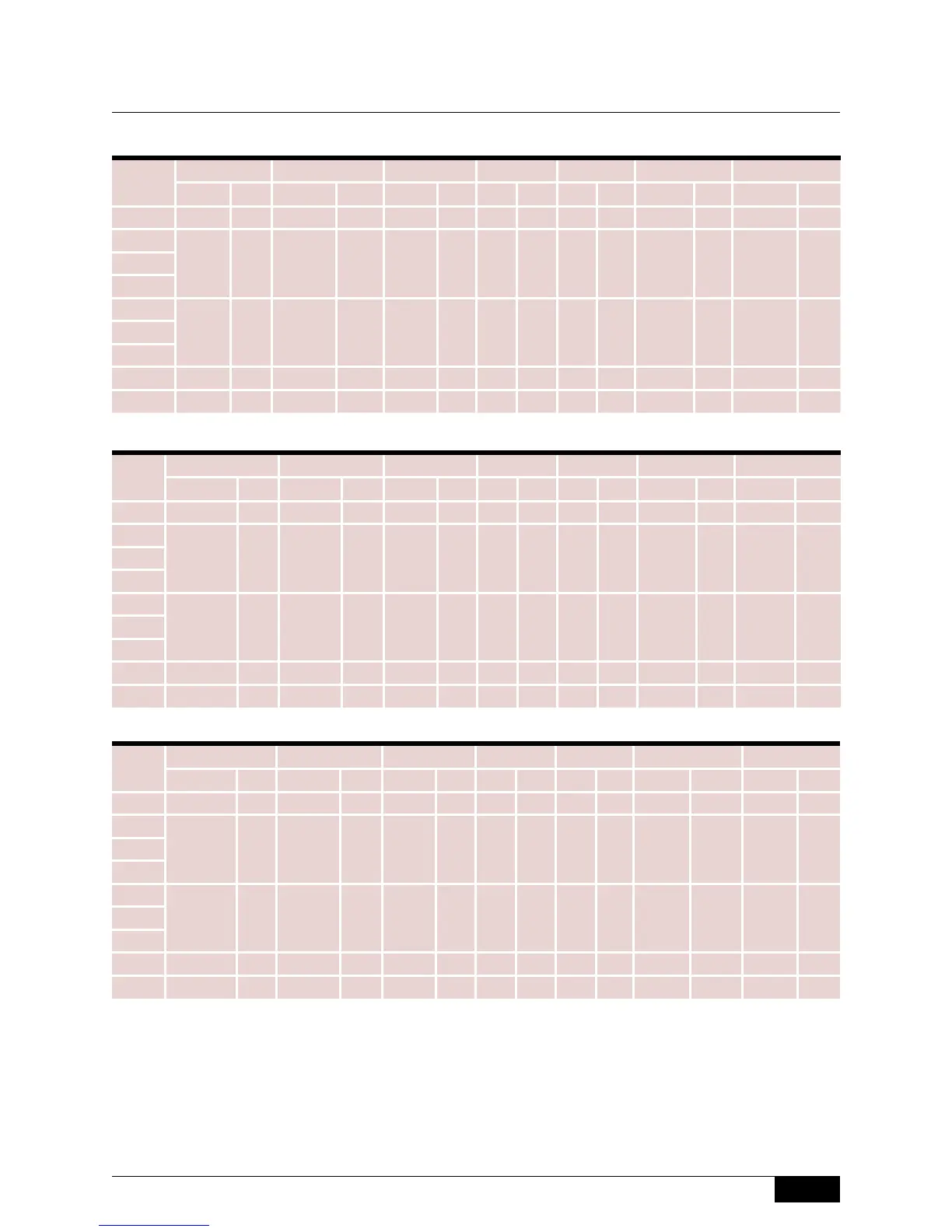
1” Connections
1-1/2” Connections
2” Connections
Chamber Dimensions
200 Series
Model
D
1, 2
E
1, 2
F
4
G H
4
I
1, 2
L
2
inch mm inch mm inch mm inch mm inch mm inch mm inch mm
201 10-1/4 260 4-13/16 122 7-7/16 189 14 356 14 356 4-9/16 116 15-3/16 386
202
10-1/2 267 3-3/4 95 6-1/2 165 14 356 14 356 3-3/4 95 14-3/8 365203
204
205
10-1/4 260 4-13/16 122 7-7/16 189 14 356 14 356 4-9/16 116 15-3/16 386206
207
209 12-5/8 321 5-13/16 148 8-7/16 214 16 406 16 406 7-1/2 191 18-1/16 459
221 9 229 3-1/4 83 6 152 14 356 14 356 3-3/4 95 14-3/8 365
Model
D
2
E
2
F
4
G H
4
I
2
L
2
inch mm inch mm inch mm inch mm inch mm inch mm inch mm
201 10-1/4 260 4-13/16 122 7-7/16 189 14 356 14 356 4-9/16 116
15-3/16
386
202
10-1/2 267 4 102 6-1/2 165 14 356 14 356 3-3/4 95 14-3/8 365203
204
205
10-1/4 260 5-1/16 129 7-7/16 189 14 356 14 356 4-9/16 116
15-3/16
386206
207
209 13-1/16 332 6-1/16 154 8-7/16 214 16 406 16 406 7-1/2 191
18-1/16
459
221 9 229 3-1/2 89 6 152 14 356 14 356 3-3/4 95 14-3/8 365
Model
D
2
E
2
F
4
G H
4
I
2, 3
L
2, 3
inch mm inch mm inch mm inch mm inch mm inch mm inch mm
201 10-1/4 260 5-3/8 137 7-7/16 189 14 356 14 356 5-9/16 141
16-3/16
411
202
10-1/2 267 4-5/16 110 6-1/2 165 14 356 14 356 4-3/4 121 15-3/8 391203
204
205
10-1/4 260 5-3/8 137 7-7/16 189 14 356 14 356 5-9/16 141
16-3/16
411206
207
209 13-3/8 340 6-3/16 162 8-7/16 214 16 406 16 406 7-1/2 191
19-1/16
484
221 - - - - 6 152 14 356 14 356 3-3/4
5
95
5
14-3/8
365
Notes
1. Dimensions D and E apply to socket-weld connections only. Consult factory for NPT dimensions.
2. Consult factory for dimensions for materials other than carbon steel.
3. Applies to socket weld or NPT process connections only.
4. Consult the factory if weld neck process flanges are required. Dimensions may vary from those shown above.
5. Applies to flanged process connections only.
 Loading...