Registered Quality System to ISO 9001:2008
46/60
Form 912
sorinc.com
913-888-2630
741A -A1C-B-A1-N4-CRTT
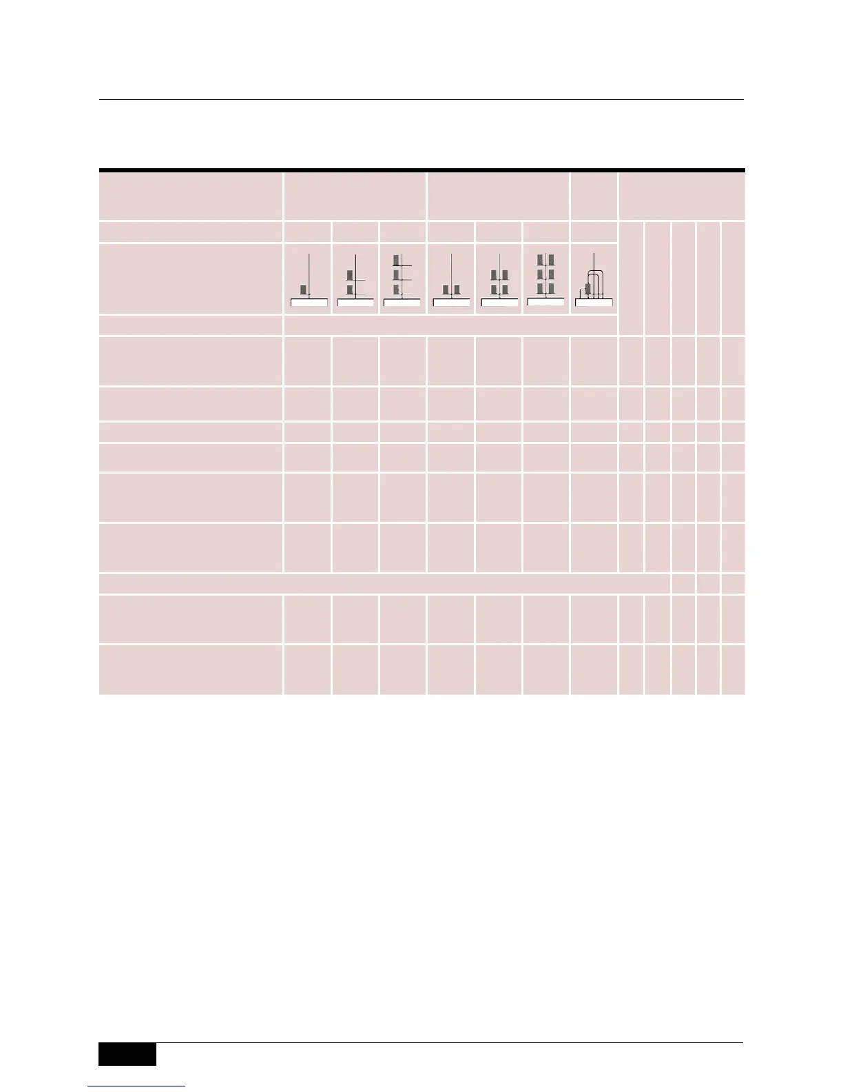
Switching Mechanisms
Select the switch mechanism from the chart below.
Notes
1. These switches use two magnets and must be considered dual mechanisms when figuring minimum
specific gravity.
2. Pneumatic switching mechanisms must be specified with P1 housing.
Mechanical
Level Switches
Switch Type
SPDT
Single Pole
Double Throw
DPDT
Double Pole
Double Throw
3-Way
Valve
Available Agency
Listings
Switching Stages Single Dual Triple Single Dual Triple Single
Switching Description Switch Designator
Standard Dry Contact
High-Temperature Dry Contact
Gold Contact
A1
B1
C1
A2
B2
C2
A3
B3
C3
A4
B4
C4
A5
B5
C5
A8
B8
C8
-
-
-
Anti-Vibration Dry Contact
1
High-Amperage DC Service
D1
1
E1
-
E2
-
E3
D4
1
E4
-
E5
-
E8
-
-
Standard Mini-Hermetically Sealed
L1 L2 L3 L4 L5 L8 -
Anti-Vibration Gold Contact
1
R1
1
- - R4
1
- - -
Gold Contact Mini-Hermet
Anti-Vibration Mini-Hermet
1
High-Temperature Mini-Hermet
S1
T1
1
V1
S2
-
V2
S3
-
V3
S4
T4
1
V4
S5
-
V5
S8
-
V8
-
-
-
Extra-High Temperature (Ceramic)
Pneumatic Non-Bleed with 316SS
Fittings
Y1
1
-
-
-
-
-
Y4
1
-
-
-
-
-
-
J0
1,2
Available with models:
Series 100-200-300-740-800
Series 108/208-400
Series 700
Series 730
Series 750
(enclosures N1, N8 or B5 only)
CSA
UL
ATEX
(flameproof)
ATEX
(IS)
TestSafe
 Loading...