Registered Quality System to ISO 9001:2008
8/60
Form 912
sorinc.com
913-888-2630
Internal
Trim
Material
The level switch model number is divided into seven sections that individually specify the
components of an SOR level switch. This diagram illustrates the model number arrangement.
Select the component designators from the appropriate pages of this brochure. Standard
components and ratings are highlighted throughout the brochure for ease of use.
Each section includes a valid model number at the top of each listing of component designators.
The position of the designator listed below it will be shown in color for reference.
How to Order
Steps 1 through 5 are required; Step 6 is optional. Orders must have complete model numbers,
i.e. each component must have a designator.
Step 1: Select Model Series based on maximum working pressure and minimum
specific gravity.
Step 2: Select Chamber Material.
Step 3: Select Process Connection.
Step 4: Select Trim Material.
Step 5: Select Switch Mechanism & Housing. (Pages 44 through 48).
Step 6: Select Accessories as required for service. (Page 49).
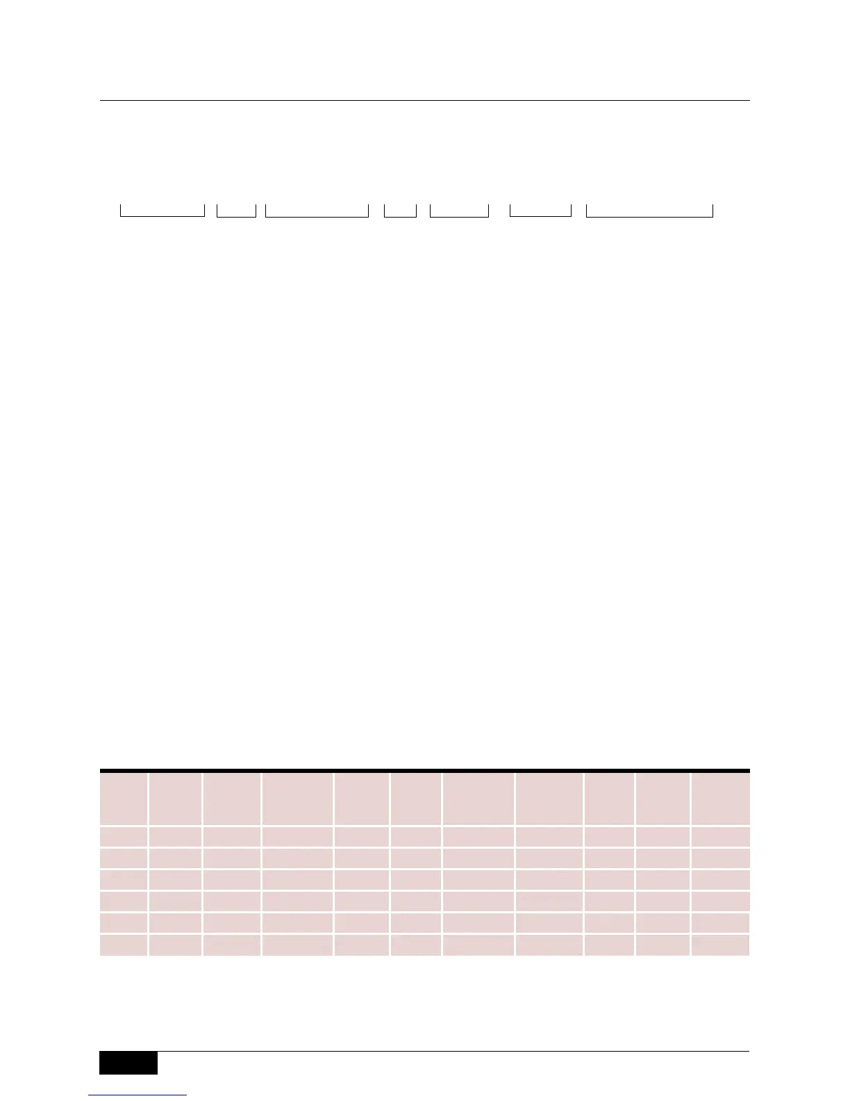
Page Numbers for Selected Steps
How to Order
101 A-A1C-B-A1-N4-CRTT
Model Number System
Model Series
Chamber
Material
Switch
Mechanism
Process Connection Housing Accessories
Mechanical
Level Switches
Step
100
Series
200
Series
108/208
Series
300
Series
400
Series
741-743,
802
Series
740 and
804
Series
700
Series
730
Series
750
Series
1 9 14 18 20 23 26 30 33 36 40
2 10 15 18 20 23 26 30 33 36 40
3 10 15 18 21 24 27 31 34 37 41
4 10 15 18 21 24 27 31 34 37 41
5 44-48 44-48 44-48 44-48 44-48 44-48 44-48 44-48 44-48 44-48
6 49 49 49 49 49 49 49 49 49 49
Design and specifications are subject to change without notice. For latest revision, see www.sorinc.com.
 Loading...