Registered Quality System to ISO 9001:2008
55/60
Form 912
sorinc.com
913-888-2630
MC and TC Options
702A-AIC-B-A1-MC-CRTT
Manual Check (MC) and Tru-Check (TC) options permit manual actuation of vertical displacer level
switches, addressing EPA and OSHA safety requirements. The standard 30-foot stainless steel
chain allows manual actuation from the tank base, eliminating potentially hazardous trips to the top
of the tank. Specify either an MC or TC option by placing the designator in the accessory section of
the model number.
These options are available on SOR level switch Series 701 through 704 and 730 through 733. MC and
TC option available on carbon steel units only. Series 730 through 733 are more sensitive to both high
and low SG values. Please consult factory before ordering the MC or TC options for these models.
How It Works
Pulling the handle transfers downward motion to the actuator lever by means of the beaded
stainless steel chain. The resultant motion lifts the entire level sensing assembly which moves
the attraction sleeve and actuates the switching element to simulate a high-level condition.
Switching action for alarm, shutdown or control is verified.
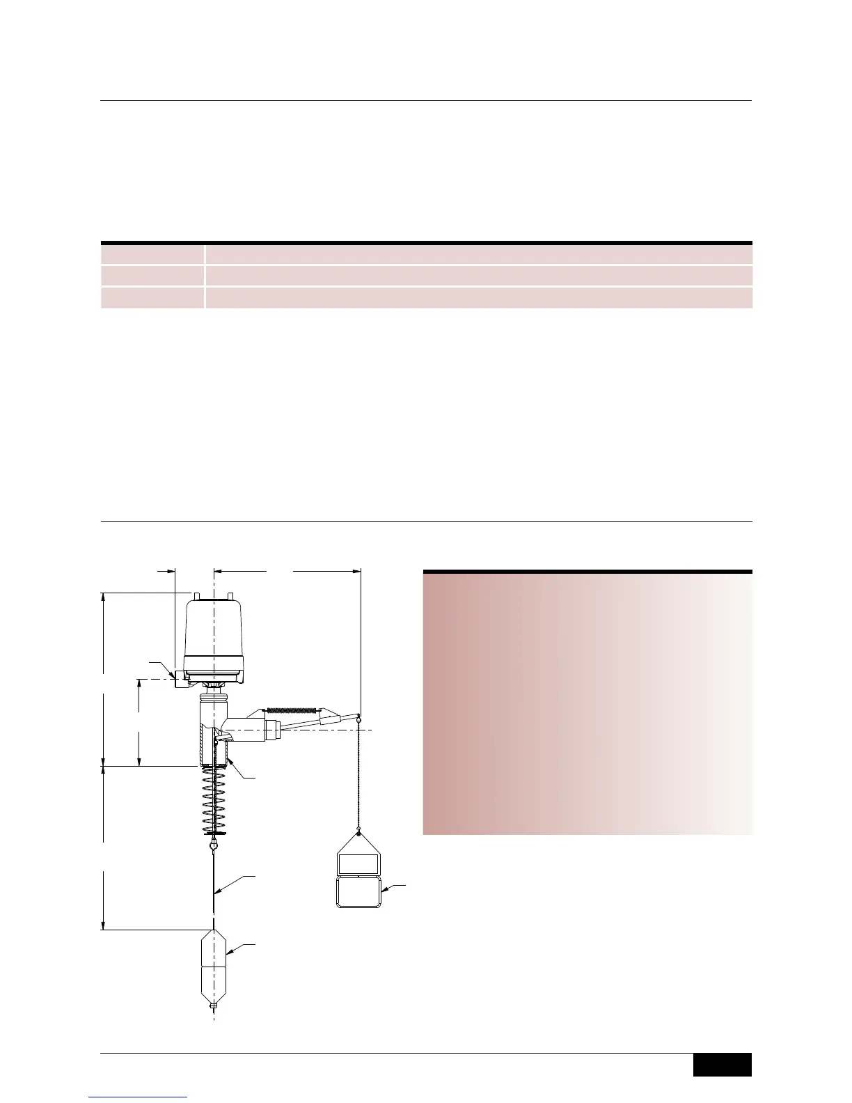
Dimensions
Mechanical
Level Switches
Designator Application
TC Tanks or vessels pressurized to 100 psi
MC Atmospheric vented tanks or vessels
Product Specifications
Pressure Range
TC (Tru-Check) *0 to 100 psi
MC (Manual Check) 0 psi (vented to atmosphere)
*Maximum pressure for entire level sensing assembly
is 100 psi with Tru-Check installed.
T
emperature Range -40 to 300°F (–40 to 150°C)
Wetted Parts
Ball Chrome Plated Brass
Seal Teflon
Spring Spring Steel
Body 1018 Steel
Design and specifications are subject to change without notice.
For latest revision, see www.sorinc.com.
ISO-9001
14685 W 105TH ST LENEXA, KS 66215 USA
913-888-2630
SORINC.COM
101.6
4.00
229.4
9.03
*456.4
17.97
393.7
15.50
CUSTOMER
SPECIFIED
DIMENSION
Model Name: 0390674.ASSEM/1/5+
PRODUCT CERTIFICATION DRAWING
ALL DIMENSIONS ARE ±1/16 IN
UNLESS OTHERWISE SPECIFIED
MM
LINEAR =
IN
DRAWN BY
K MITCHELL
CHECKED BY
M SMITH
ENGINEER APPROVAL
J FIFE
DATE
16 MAY 2011
THIS DRAWING IS THE EXCLUSIVE PROPERTY OF SOR.
NO USE WHATSOEVER OF THE INFORMATION CONTAINED
HEREON, NOR REPRODUCTION IN WHOLE OR PART MAY BE
MADE WITHOUT THE EXPRESS WRITTEN PERMISSION OF SOR.
TITLE
DIM DWG 700 SERIES W/MANUAL CHECK
EO NUMBER: 5116
SCALE: 0.20
DO NOT SCALE PRINT
DRAWING NUMBER REV
0390674 3
SHEET 1 OF 1
DWG SIZE
B
MODEL # SALES ORDER # LINE ITEM # PURCHASE ORDER #
ELECTRICAL
CONNECTION "W"
146.1
* MINIMUM OVERHEAD CLEARANCE
5.75
REQUIRED TO REMOVE HOUSING COVER
PROCESS
CONNECTION
2-1/2 NPTM OR
4" 150# FLANGE
(NOT SHOWN)
W
316 SST
CABLE
HANDLE
DISPLACER
Drawing 0390674
 Loading...