Registered Quality System to ISO 9001:2008
29/60
Form 912
sorinc.com
913-888-2630
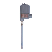
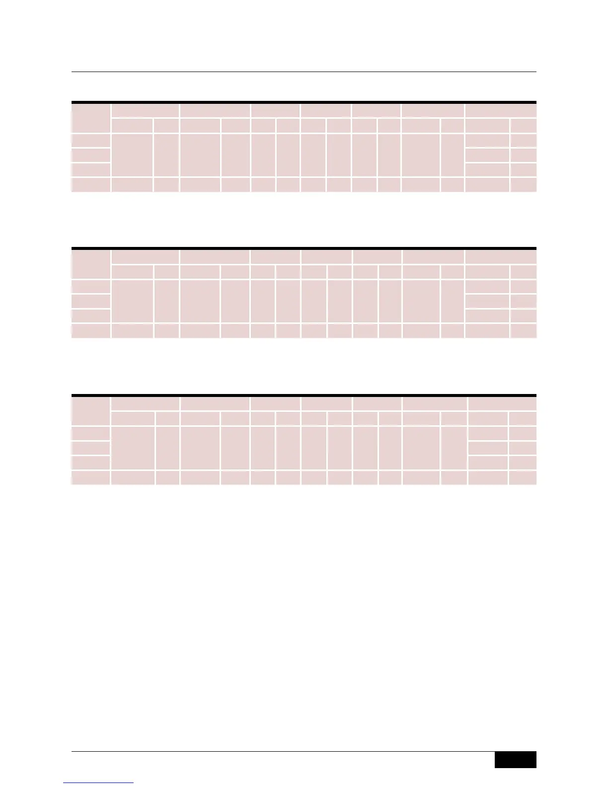
Chamber Dimensions
1” Connections
1-1/2” Connections
2” Connections
741-743 and
802 Series
Model
D
1, 2
E
1, 2
F
4
G H
4
I
2
L
2
inch mm inch mm inch mm inch mm inch mm inch mm inch mm
741
13 330 3-1/4 83 6 152 16 406 16 406 3-3/4 95
19-5/16 491
742 19-1/2 495
743 19-7/8 505
802 12-3/4 324 3-7/8 98 8 203 16 406 16 406 6-3/4 171 20-3/4 527
Model
D
2
E
2
F
4
G H
4
I
2
L
2
inch mm inch mm inch mm inch mm inch mm inch mm inch mm
741
13 330 3-1/2 89 6 152 16 406 16 406 3-3/4 95
19-5/16 491
742 19-1/2 495
743 19-7/8 505
802 12-7/8 327 4 102 8 203 16 406 16 406 6-3/4 171 20-3/4 527
Model
D
2
E
2
F
4
G H
4
I
2, 3
L
2, 3
inch mm inch mm inch mm inch mm inch mm inch mm inch mm
741
- - - - 6 152 16 406 16 406 3-3/4
5
95
5
19-5/16
5
491
5
742 19-1/2
5
495
5
743 19-7/8
5
505
5
802 13-3/16 335 4-5/16 110 8 203 16 406 16 406 7-3/4 197 21-5/16 541
Notes
1. Dimensions D and E apply to socket-weld connections only. Consult factory for NPT dimensions.
2. Consult factory for dimensions for materials other than carbon steel.
3. Applies to socket weld or NPT process connections only.
4. Consult the factory if weld neck process flanges are required. Dimensions may vary from those shown above.
5. Applies to flanged process connections only.
 Loading...