10
1.Select necessary program/hydraulics
(Resp. D.1 - Hydraulic variants)
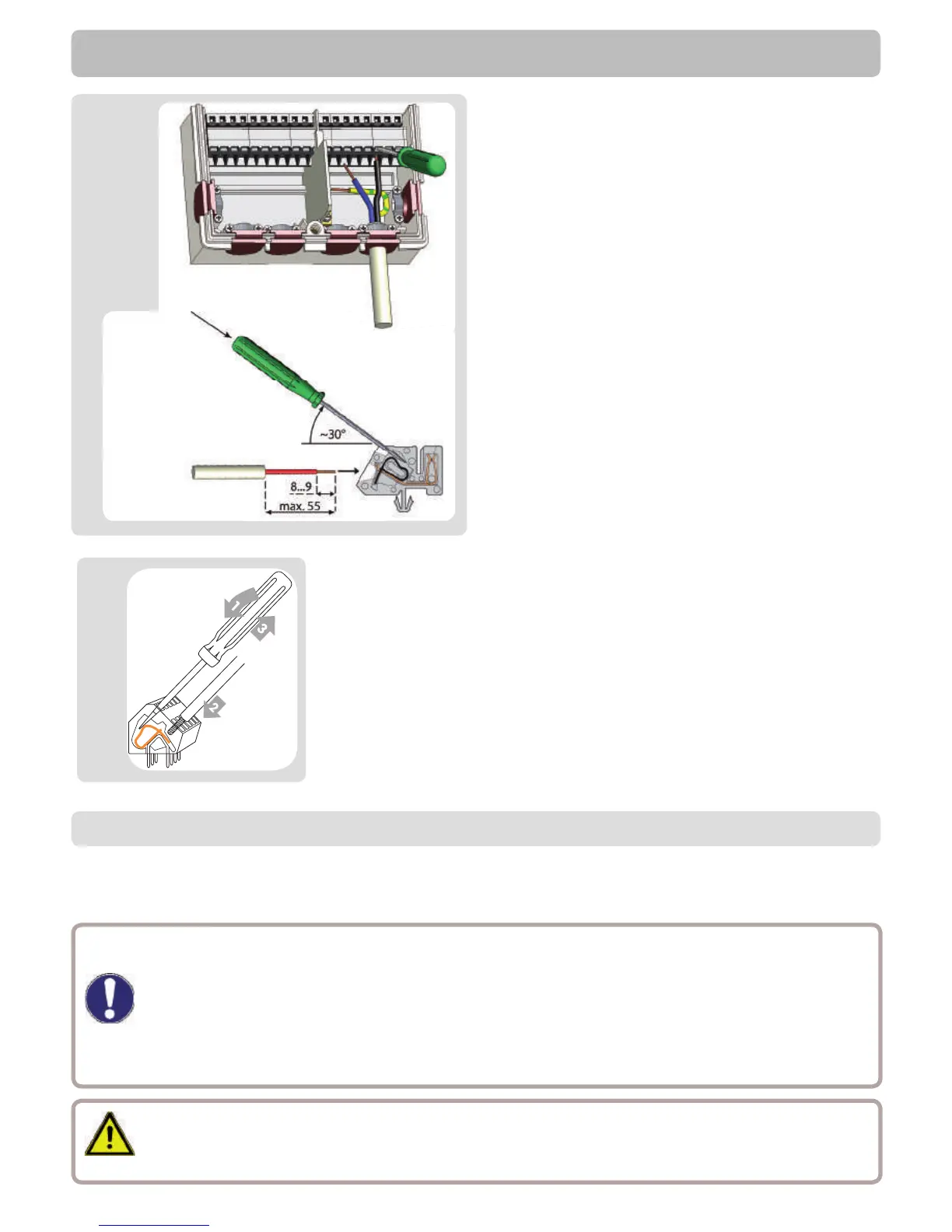
2.Strip cables by 55 mm max., insert,
t the strain relief devices, strip the last
8-9mm of the wires (Fig. C.2.1)
3.Open the terminals using a suitable
screwdriver (Fig. C.2.1) and make electri-
cal connections on the controller (s. D.1)
4.Re t upper part of housing and fasten
with screw.
5.Switch on mains voltage and place con-
troller in operation.
C.2.1
Installation
C.3 Installing the temperature sensors
The temperature sensor cables must be routed separately from mains voltage
cables, and must not, for example, be routed in the same cable duct!
The controller operates with Pt1000 temperature sensors which are accurate to the
degree, thus ensuring optimal control of system functions.
If desired the sensor cables can be extended to a maximum of 30 m using a
cable with a cross-section of at least 0.75 mm². Make sure that there is no con-
tact resistance! Position the sensor precisely in the area to be measured!
Only use immersion, pipe-mounted or at-mounted sensor suitable for the spe-
ci c area of application with the appropriate permissible temperature range.
Caution
Caution
Instructions for clamps:
1. Insert screw driver into the upper hole. Push the lock
clamp inside down. Keep the screw driver in this positi-
on.
2. Insert cable into the lower opening.
3. Remove screw driver. The clamp will lock the cable.
C.2.2