14
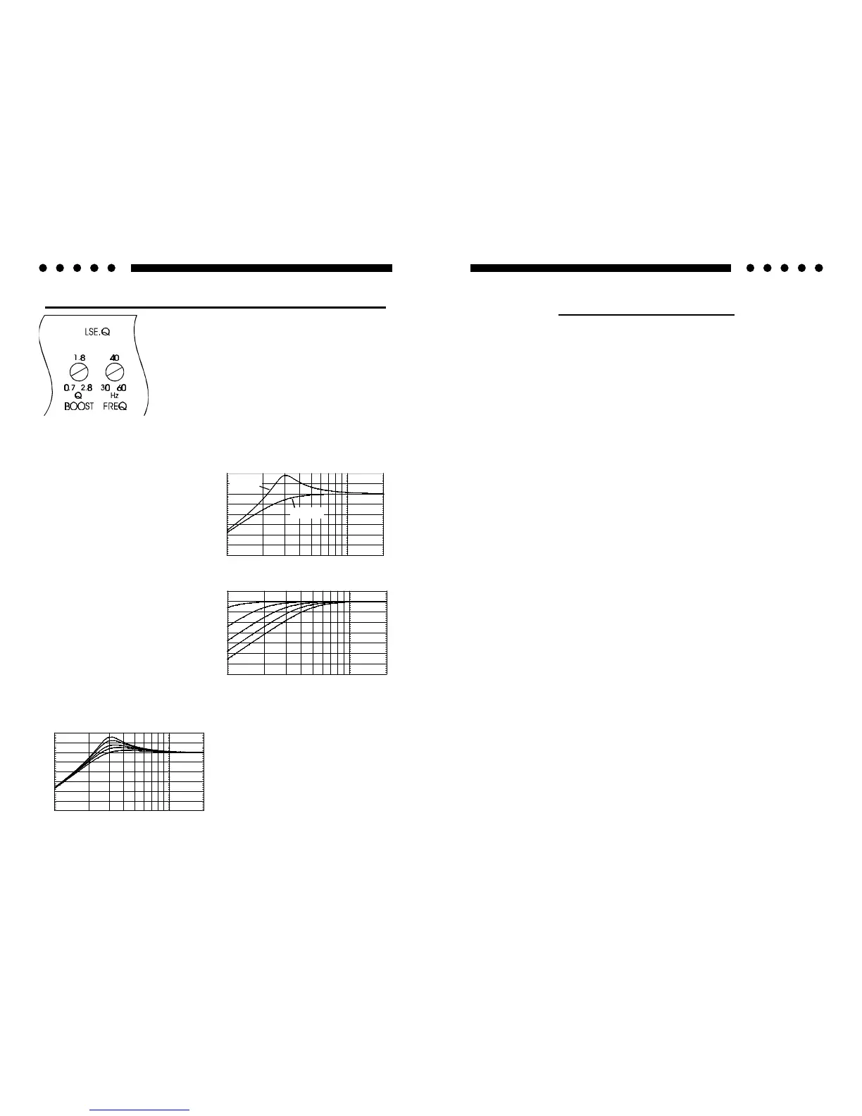
LSE.Q THEORY AND USE (Reference1000s)
LSE.Q is a unique subwoofer control circuit
included with the SOUNDSTREAM
REFERENCE1000s amplifier. It is capable of
removing subsonic energy in program material.
The circuit consists of two controls. One adjusts
the frequency of operation and the other adjusts
the range of boost. With both controls adjusted
fully counter-clockwise, no boost is applied and
the amplifier is flat in response down to 30 Hz.
The frequency control (Hz) adjusts the starting point of the subsonic
filter. This high pass filter can be adjusted from 30 Hz up to a
maximum of 60 Hz. This control
is useful for setting the lowest
frequency that your subwoofer will
see. (See figure 1)
The Q control adjusts the
amount of boost applied at the set
frequency. This is adjustable
from .707 (flat) to 2.8 (+9 dB).
(See figure 2)
When the Q is set to .707
(Butterworth), LSE.Q acts as a
sub-sonic filter only. (See figure
3)
The simple act of removing the
signal below the vented tuning
frequency can improve system
output by as much as 3 dB. With
Q values greater than .707, boost
is added to the sub-sonic filter. (see figure 4)
Application
Woofers in vented enclosures have
good power handling characteristics
above the tuning frequency, but
below the tuning frequency, power
handling drops off considerably.
This is due to the loss of any
appreciable resistive air mass. At
-10
Frequency (Hz)10
-30
-25
-15
-20
-5
dB
0
5
10
50 100 200
FIG. 3 Variable High Pass
FIG. 1 LSE.Q
dB
Frequency (Hz)
-20
-30
10
-25
-15
-10
5
0
-5
10
50 100 200
FIG. 2 Variable “Q”
Q=2.8
Q=0.707
dB
Frequency (Hz)
-20
-30
10
-25
-15
-10
5
0
-5
10
50 100 200
FIG. 4 Variable “Q”
11
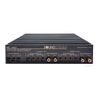
Key to Callouts
1. Fault LED - Indicates a blown fuse.
2. High Power LED - Indicates amplifier power on in "High Power" mode.
3. Auto High Current LED - Indicates amplifier power on in "High Current"
mode.
4. Line Out Crossover Switch - Select high pass, low pass or full range low
level output to an auxiliary amplifier.
5. LSE.Q Bypass Switch - Turns the LSE.Q on ("IN") or off ("OUT").
6. Input Overload Indicators - Indicates the signal input level or input gain
level is too high.
7. Input Level Selector Switch - Selectable input sensitivity range from 0.2-
2 Volts RMS, or from 0.5-5 Volts RMS.
8. Left Channel Balanced / Unbalanced Input Selector Switch - Select
"Balanced" to use the 6 pin Balanced signal input. Select "Unbalanced" to
use the RCA signal inputs.
9. Right Channel Balanced / Unbalanced Input Selector Switch - Select
"Balanced" to use the 6 pin Balanced signal input. Select "Unbalanced" to
use the RCA signal inputs.
10. Main Fuse - Main power supply fuse. Replace only with the same value
fuse.
11. +12V - Connected to a fuse or circuit breaker, then to the battery's positive
post.
12. GND - Main ground connection. Bolt to a clean chassis ground in the
vehicle.
13. REM - Remote turn-on input from the head unit. Accepts +12V.
14. Speaker Output Connections - Left and right channels.
15. Crossover Output - High pass, low pass or full range output to an
auxiliary amplifier.
16. Crossover Adjustment Pots - Crossover frequency settings for high
pass and low pass filters; Amplifier and crossover outputs.
17. LSE.Q - Frequency and Q adjustments.
18. Input Level - Independent Left and Right channel input level controls.
19. Balanced Signal Input Connector - 6-pin Balanced signal input
connector for use with the Soundstream BLT Balanced Line Transmitter.
20. Inputs - Right and left channel RCA (Unbalanced ) inputs; only right
channel input is used in "Mono" mode.
21. Coherent Stereo/Bridge/Mixed Mono switch - Select "Bridge" for
bridged mono operation (use right channel input). Select "Stereo" for
coherent stereo operation. Select "Mixed Mono" for simultaneous stereo /
bridged mono operation.
22. Amplifier Crossover - Select high pass, low pass or full range amplifier
operation.
 Loading...