4
DESIGN FEATURES
• Uncompromising Design and Construction including mil-spec
glass epoxy circuit boards and high current custom gold-plated solid
brass connections that will accept up to 4 gauge power/ground wire.
• Auto High Current™ - Soundstream’s newest exclusive circuit which
automatically customizes your amplifier to its particular application—
High Current, low impedance loads (multiple subwoofers, less than 2
ohms mono) or High Power, higher impedance loads (2 ohms mono
and up).
• Coherent Stereo
TM
/Mixed Mono selection for either “pure” stereo
operation or mixed mono for simultaneous stereo and mono.
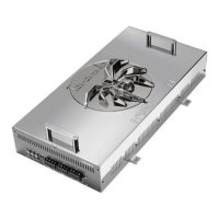
• Chassisink
TM
Darlington Power Array - Soundstream’s
“overbuilding” of the output section incorporates multiple output
transistors instead of a few for faster, stronger power delivery. The
transistors are sandwiched between the circuit board and the heatsink
in a design called Chassisink
TM
to ensure cool, efficient amplifier
operation.
• PowerGrid Power Supply Design - All power supply components
are located near one another, connected by thick, wide PCB traces,
which ensures rapid, high current delivery. The entire power supply is
isolated on one side of the circuit board while the audio stage is
located opposite it, guaranteeing minimal noise.
• Ultra-Low ESR Capacitance Bank - Multiple small input power
capacitors are used to provide a lower ESR (Equivalent Series
Resistance), which means more power in and out faster.
• Smart Thermal Rollback - Most amplifiers shut off when they get too
hot. In the unlikely event the REFERENCE amplifier reaches 85° C,
it will gradually roll back its average power (without affecting the
dynamics). Once the amplifier has cooled off, it returns to full power
output. If overheating should continue, a second thermal sensing
protection circuit will shut off the amplifier if the heatsink reaches 95°
C.
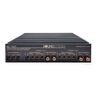
• Fault Monitor LED on the top panel notifies you of blown power
supply fuses.
• 1/2 ohm Drive Ability - The REFERENCE amplifiers are designed to
21
LEVEL SETTING
The input levels are adjusted by means of the individual channel input level
controls located on the front of the amplifier. This is a unique dual-stage
circuit that adjusts both level and gain. This topology maintains better Signal
to Noise ratios even when using sources with minimal output.
In the ideal situation, all components in the audio system reach maximum
undistorted output at the same time. The reason is because an amplifier will
only make what comes into it bigger. So, if you send it a distorted signal from
the head unit, the amplifier is going to amplify distorted information. The
same thing holds true if an outboard processor or crossover begins to distort
before you have maximum output from the amplifier. By setting all
components to reach clipping at the same time, you can maximize the output
of your system. For the REFERENCE amplifiers, follow the following steps for
the quickest, easiest means of setting the levels.
INSTALLATION STEP 5
1. Turn the amp’s input levels to minimum position (fully counter-
clockwise).
2. Begin with the input level switch in the 0.5 - 5.0 Volt position.
3. Set source unit volume to approximately 3/4 of full volume.
4. While playing dynamic source material, slowly increase the amplifier’s
input level until a near maximum undistorted level is heard in the
system.
If your preamplifier / source unit has an extremely high output level, be sure to
pay attention to the clipping indicators located on the top of the amplifier.
These indicators will notify you if you are clipping the PREAMPLIFIER stage of
the amplifier. If the amplifier's output is distorted and the clipping lights are
not blinking, you are most likely clipping the OUTPUTS of the amplifier, or
driving the speaker to distortion.