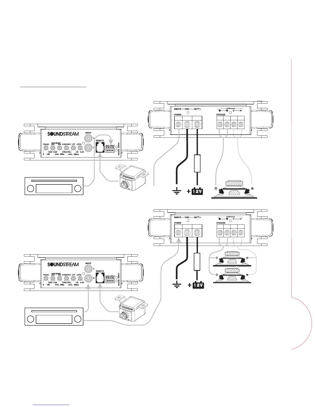
Fig 12. Mono amplifier wiring
WIRING DIAGRAM
(High level input mode)
Fig 13. Mono amplifier wiring
(multi woofers)
ON/OFF
control signal
Speaker signal
*Equivalent parallel woofer load cannot be
less than the minimum load rating. The 2
negative terminals are paralleled inside the
amplifiers, as are the 2 positive terminals.
These are monoblock amplifiers, not multi-
channel amplifiers.
FUSE
Source Unit
FUSE
Source Unit
REMOTE
si
gna
l
RCA signal
WIRING
 Loading...