14
OPERATION cont.
Note: Test bend should be performed to ensure proper squeeze is set.
Minor adjustments may be required. To make adjustments to the squeeze set-
ting, refer to section labeled “SQUEEZE ADJUSTMENT”.
BENDING cont.
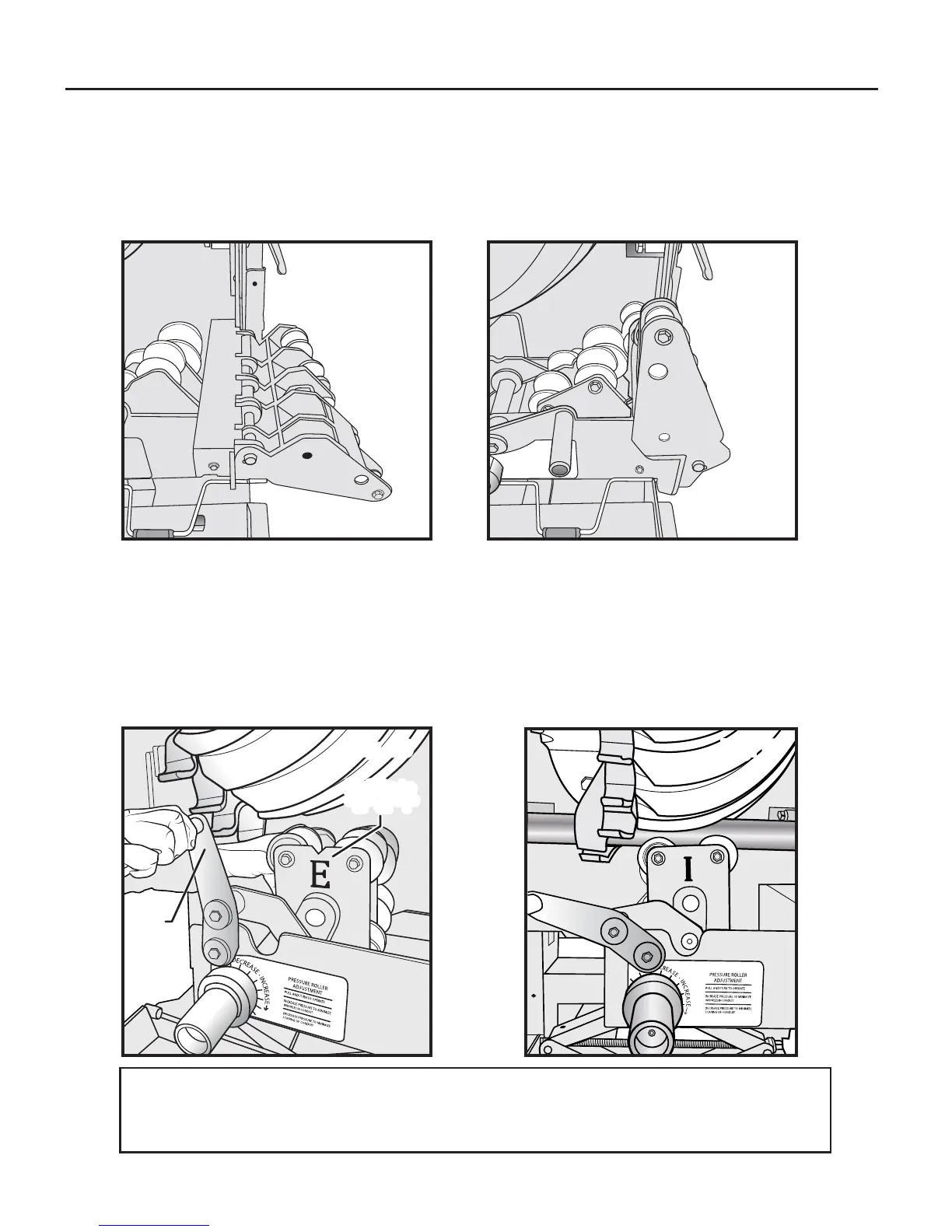
4. Bending the conduit
4A. For 3/4” through 1
1
/4” EMT, IMC, or rigid conduit, ensure the 3/4”- 2” Rollers (7)
are in the upright position, as shown in (Figs. 14, 15). For 1
1
/2
”
- 2
”
rigid conduit
sizes utilize the 3/4”- 2” rollers (7) while in the upright position.
4B. For 1
1
/2” and 2” EMT or IMC conduit, use the 1
1
/2”- 2” EMT and IMC
Roller (14) by turning the assembly to reflect “E” for EMT or “I” for IMC.
EMT and IMC Roller Lock Handle (13) may have to be pulled to the left to
allow roller assembly to be rotated (Fig 16). Once properly selected, raise
the rollers from the retracted position to the upright (engaged) position by
rotating the EMT and IMC Roller Lock Handle (13) counter clockwise to lock
and secure conduit in place, as shown in (Fig 17).
Fig. 14
Fig. 15
Fig. 17Fig. 16
Pull
handle
to left
Rotate to
“E” or “I”
Rotate to
“E” or “I”