Setup
91518 Multigas Analyzer Service Manual 2-8
90364, 90491, 90499, and 90387 Module Housing or Monitor Installations
To install the 91518 with 90364, 90491, 90499, and 90387 module housings or monitors:
1 Verify that the AC power is connected as required by local standards. The 91518 Multigas Analyzer will not
require the use of an external power supply.
2 Ensure that the monitor or module housing and multigas analyzer are powered OFF.
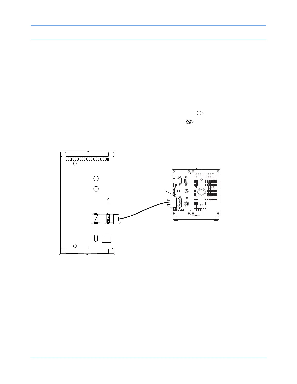
3 Assemble the required cables for your system configuration (refer to Figure 2-8 for part numbers).
4 Connect the SDLC cable (P/N 012-0601-xx) to the SDLC jack (J3) on the 91518 rear panel (refer to
Figure 1-3 on page 1-5 for rear panel information) and to the SDLC (J2) of the monitor or module housing.
5 Set the SDLC switch on the 90364/90491/90499/90387 to unterminated ( ).
6 Set the SDLC switch on the 91518 Multigas Analyzer to terminated ( ).
Figure 2-8: 91518 connections to 90364, 90491, 90499, and 90387 monitors or housings
J2
J3
P/N 012-0601-xx
SDLC
jack (J3)
cable
90364/90491/
90499/90387
91518
 Loading...