91518 Multigas Analyzer Service Manual 2-11
Setup
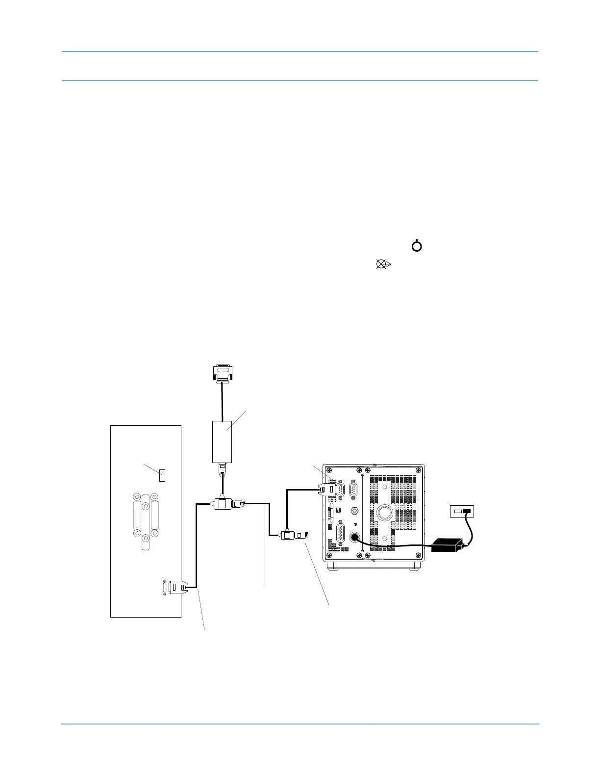
90485 Remote Module Housing Installation with Flexport
1 Verify that AC power is connected as required by local standards. An external power supply
(P/N
119-0480-00 or 119-0251-00) is required for use with the 91518 Multigas Analyzer.
2 Ensure that the module housing and multigas analyzer are powered OFF.
3 Assemble the required cables for your system configuration (refer to Figure 2-11 for part numbers).
4 Connect the P1 connector of the tee cable (P/N 012-0175-01) to the SDLC jack (J2) on the 91518 rear panel
(refer to
Figure 1-3 on page 1-5 for rear panel information).
5 Connect P3 of the Flexport cable (P/N 012-0152-00) to P2 of the tee cable (P/N 012-0175-01).
6 Connect P1 of the Flexport cable to the remote module housing.
7 Set the SDLC switch on the 90485 remote module housing to unterminated ( ).
8 Set the SDLC switch on the 91518 Multigas Analyzer to terminated ( ).
Note:
If using more than one Flexport, Spacelabs Healthcare recommends the use of the Flexport Holder
(P/N
650-0201-00).
Figure 2-11: 91518 connections to a remote module housing
J6
90485 Remote
SDLC
jack (J2)
91518
Module Housing
AC power
Power supply
P/N 119-0480-xx
P/N 012-0175-01
tee cable
P/N 012-0152-00
tee cable
SDLC
termination
switch
To peripheral device
Flexport interface
SDLC
terminator
P/N 012-0507-02
 Loading...