91518 Multigas Analyzer Service Manual 3-5
Theory
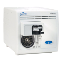
D-fend Water Trap
The gas sample is drawn through a sampling line. The gas then enters the analyzer through the water trap,
where it is divided into two flows, a main flow and a side flow.
The main flow enters the analyzers and is separated from the patient side by a hydrophobic filter. The side flow
creates a slight subatmospheric pressure within the D-fend water trap, which causes fluid removed by the
hydrophobic filter to collect in the bottle.
Zero Valve and Absorber
The main flow passes through a magnetic valve before proceeding to the analyzers. This valve is activated to
establish the zero points for the gas measuring unit and the oxygen measuring unit. When the valve is
activated, room air is drawn through the absorber into the internal system and the gas sensors. Paralyme is
used as an absorbent.
Nafion Tubes
A nafion tube is used between the water trap and the zero valve to balance the sample gas humidity with that
of ambient air. The tube will prevent errors caused by the effect of water vapor on gas partial pressure when
humid gases are measured after calibration with dry gases.
Another nafion tube is used between the absorber and the pneumatic unit to prevent humidity caused by
absorption of CO
2
.
Gas Analyzers
After flowing through the zero valve and nafion tube, the gas flows through the gas measurement and oxygen
measurement (OM) units. The oxygen sensor has two inputs. One input accepts the main flow, and the other
draws in room air for reference, from the Ref port. Both gas flows exit from a single port.
Sample Flow Differential Pressure Transducer
The sample flow differential pressure transducer measures pressure drops across the OM inlet restrictor and
calculates the sample flow from the pressure difference.
Working Pressure Transducer
The working pressure transducer measures absolute working pressure between the gas measurement unit
and OM unit.
Pneumatic Unit
The pneumatic unit contains a zeroing valve, an occlusion valve, and tubing connections. A series of restrictors
and chambers forms a pneumatic filter that prevents pressure oscillations from the pump from reaching the
measuring units. The occlusion valve connection to room air includes a dust filter, and the zero valve
connection to room air includes an absorber.
Connection Block
The connection block contains a sample gas outlet connector and OM unit reference gas inlet (Ref). The inlet
is equipped with a dust filter.

 Loading...