Maintenance
40 EN 04/2019
8.5.5 Assembling motor
The motor and pump shafts must not be greasy!
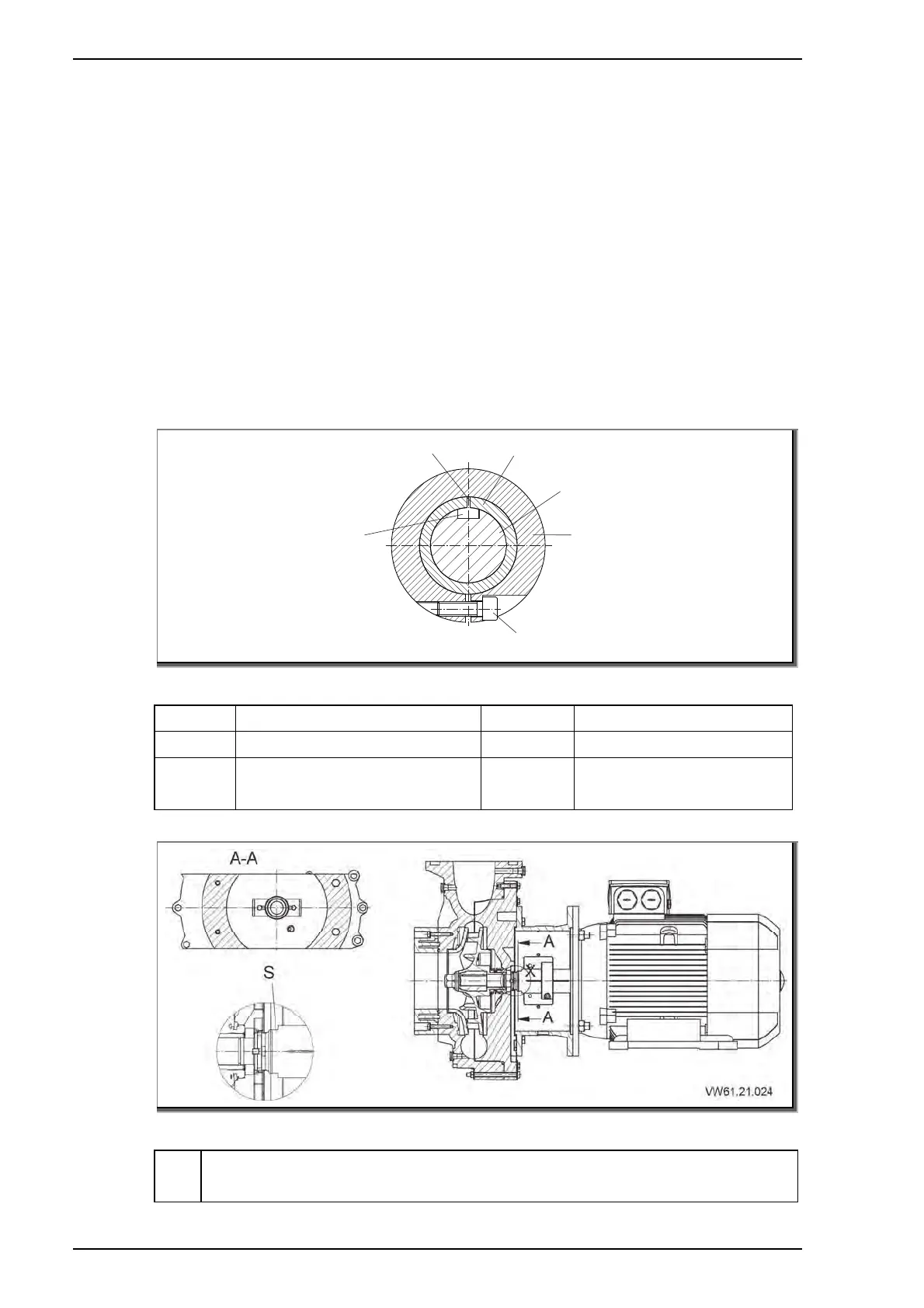
1. Plug the motor shaft end into the shaft (210). The motor shaft
key nut and t
he slit in the shaft (210) have to be congruent
and lay opposite the slit in the supporter ring (515). See "Fig.
7" on page 40
2. Tighten
the hexagon socket screw (914.1).
3. Loosen the hexagon screw (901.3).
4. Pull both lockwashers (931) completely out of the shaft nut.
Se
e "Fig. 8" on pag
e 40
5.
Tighten
the
hexagon screw (901.3).
6. Attach and tighten the nuts (920.5).
914.1
515
800
210
X
Y
VW61.21.023
Fig. 7
X Slit in the shaft 515 Support rin
Y Motor shaft key nut 800 Motor
210 Pump shaft 914.1
Hexagon socket
screw
Fig. 8
S
Opening SW 34 (BG 10
0, BG 112)
Openin
SW 46
BG 132, BG 160, BG 180