EPOCH 35 GNSS System User Guide 15
Setup, Connection, and Cabling 2
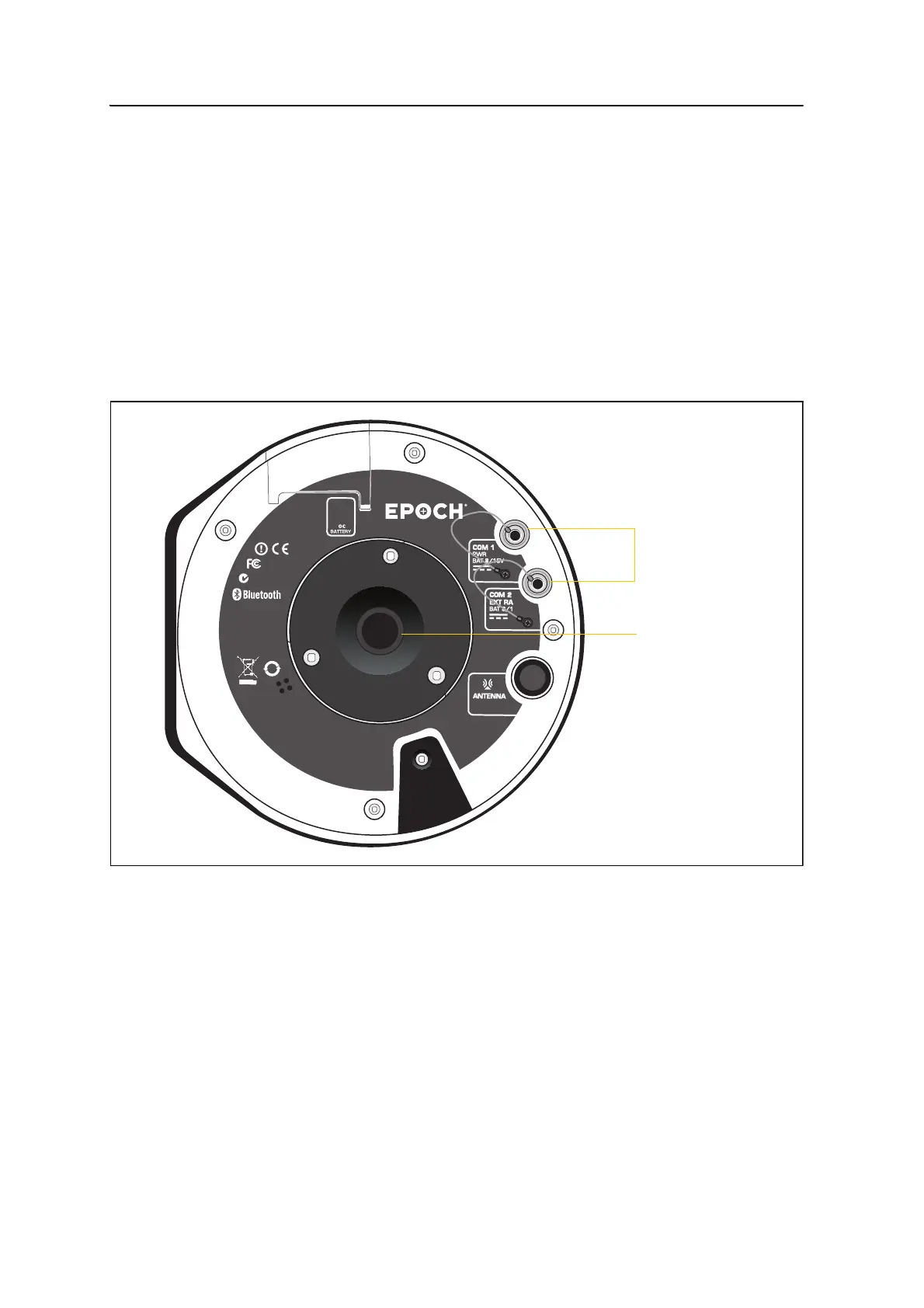
2.2 Parts of the rover receiver
All operating controls on the receiver are located on the front panel. Serial ports and
connectors are located on the bottom of the unit.
• The power button controls the receiver’s power on or off functions.
• LEDs show the status of power, satellite tracking, and radio reception. See also
LED display, page 25.
22.1 Ports and connectors
Figure 2.2 shows the two serial ports and the
5
/
8
-11 threaded insert.
Figure 2.2 Ports and connectors on the rover
• COM 1 is a 7-pin 0-shell LEMO connector that supports RS-232
communications and external power input. Port 1 has no power outputs and
external power input of 8–15 V.
• COM 2 is a 7-pin 0-shell LEMO connector that supports RS-232 . Port 2 has no
power outputs and external power input of 8–15 V.
For more information, see Chapter 5, Default Settings and Chapter 6, Cables and
Connectors.
• Use the TNC connector (not shown) to connect the radio antenna.
inf
ormatio n.
N324
For home
and office us e.
[
[
FCC ID: QOQ-WT12
IC: 5123A-BGTWT12A
Bluetooth B03005
M
ade in S
PA I N
CONTAINS:
10
Spectra Precis ion
®
Serial ports
5
/
8
-11 threaded
insert