2 Setup, Connection, and Cabling
14 EPOCH 35 GNSS System User Guide
2.1 Parts of the base receiver
All operating controls on the receiver are located on the front panel. Serial ports and
connectors are located on the bottom of the unit.
• The power button controls the receiver’s power on or off functions.
• LEDs show the status of power, satellite tracking, and radio reception. See also
LED display, page 25.
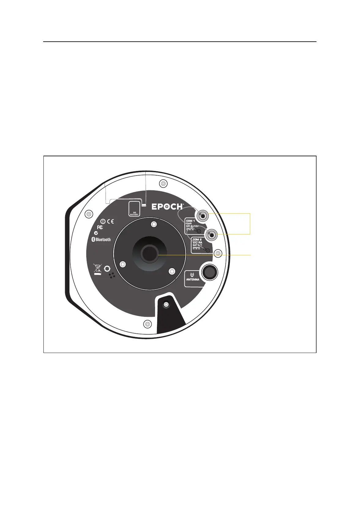
21.1 Ports and connectors
Figure 2.1 shows the two serial ports and the
5
/
8
-11 threaded insert.
Figure 2.1 Ports and connectors on the base receiver
COM 1 is a 7-pin 0-shell LEMO connectors that supports RS-232 communications and
external power input of 8–15 V. Port 1 has no power outputs.
COM 2 is a 7-pin 0-shell LEMO connector that supports RS-232 and external power
input of 8–15 V. Port 2 has no power outputs.
For more information, see Chapter 5, Default Settings and Chapter 6, Cables and
Connectors.
inf
ormatio n.
N324
For home
and office us e.
[
[
FCC ID: QOQ-WT12
IC: 5123A-BGTWT12A
Bluetooth B03005
M
ade in S
PA I N
CONTAINS:
10
Spectra Precis ion
®
Serial ports
5
/
8
-11 threaded
insert