IM-P343-22 CH Issue 2
10
Fig. 10
2.3.11 The earth cable should now be reconnected to the earth adaptor (11) and secured using
the original M4 x 8 screw (refer to Fig. 11). When correctly located, the plastic retaining
clamps can be tightened to secure the options board in place. Note: With the retaining
clips secured there will be some float of the PCB.
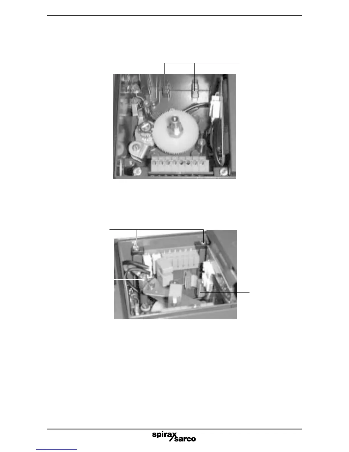
Fig. 11
Earth
connection
Ribbon cable
connector
located on
main PCB
Retaining clips
2.3.10 Loosen the option board plastic retaining clamps. Now locate the options board within
the SP2 enclosure ensuring it is correctly located within the lugs at the bottom of the
housing (refer to Fig. 10). Note: the options board should be located with terminal
connectors at the top.
Location lugs
2.3.12 Prepare the ribbon cable by ensuring it is at right angles to the options PCB. Engage
the ribbon connector onto the main PCB socket permanently pushing in place
to locate. This should be done with light finger pressure only (refer to Fig. 11) do
not apply force, (only required with 4 - 20 mA retransmit and software switch options).