IM-P343-22 CH Issue 2
11
Fig. 13
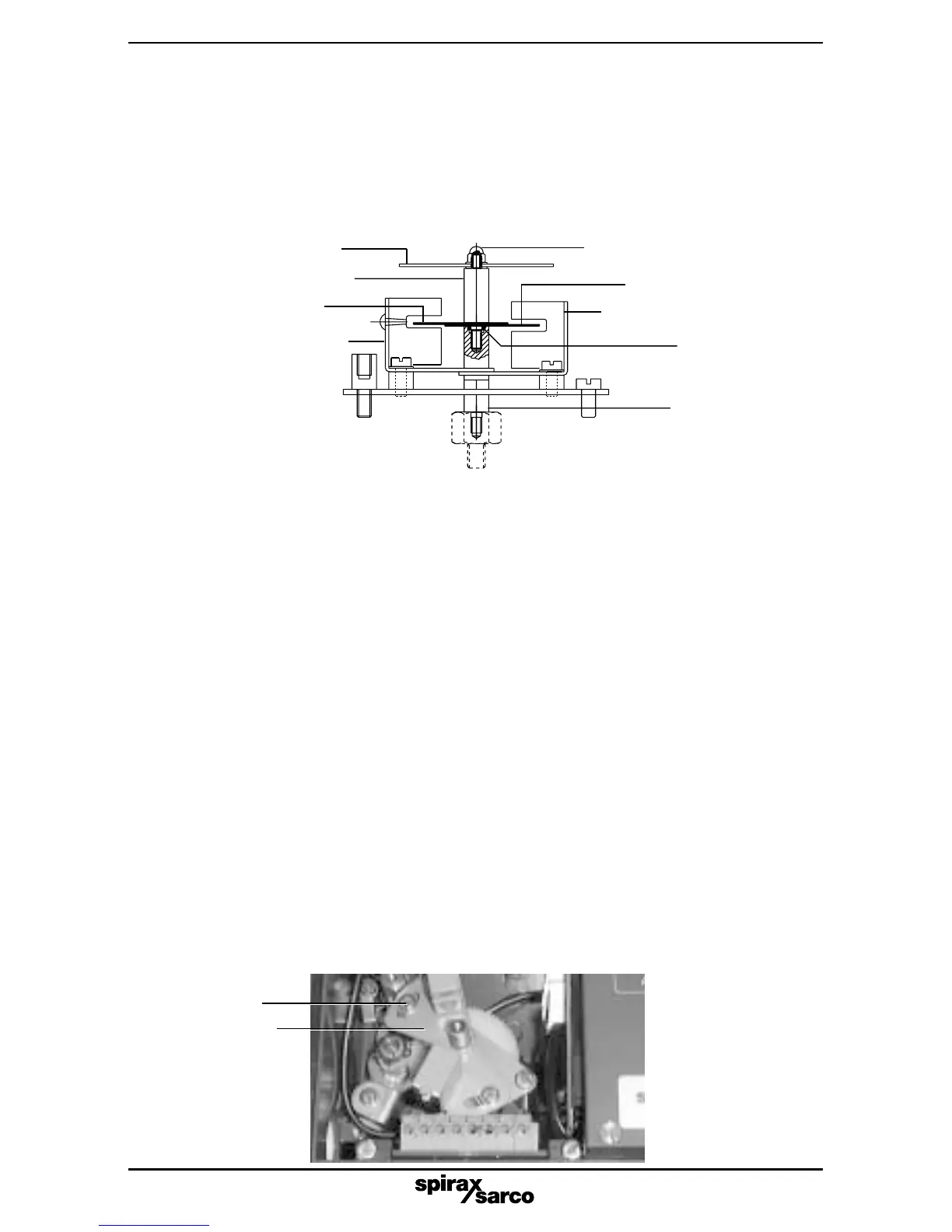
Fig. 12
2.3.13 Fit switching vanes (6) to the spindle (13) and ensure 'O' ring (10) is correctly located
within the end of the spindle. Now fit the extension spindle (12) and finger tighten to
secure in position.
It is essential that the switching vanes are correctly located within the slots of the PF1
and PF2 switches. The top vane should be positioned within PF1 switch sensor (5)
and the bottom vane positioned within the PF2 switch sensor (5) to ensure they are
positioned evenly within the slots (refer to Fig. 12).
Switching vane (6)
PF1 switch sensor (5)
Switching vane (6)
PF2 switch sensor (5)
2.3.14 It is now necessary to set the switching action. Note, adjustment of the switch vanes
provides coarse setting whilst movement of the adjustment plates (4) provides
fine setting.
For setting the Pepperl and Fuchs switches you must now mount the SP2
positioner onto the valve / actuator assembly and recommission the SP2 positioner
as described in Section 5, 'Installation' of the SP2 Installation and Maintenance
Instructions IM-P343-19.
Please note: if the SP2 positioners are supplied with Pepperl and Fuchs switches
already fitted, they will be supplied unset.
2.4 Setting Pepperl and Fuchs switches
Note: The PF1 or PF2 switch will open when the switching vane is 50% or more within
the switch sensor.
2.4.1 Coarse setting of the PF1 switch
Locate the adjustment plate (4) at its mid position and tighten the adjustment screws (9)
(refer to Fig. 13).
Position the valve at the desired switching position for PF1 switch. The valve can be
positioned using manual control (M-CTL) in conjunction with the digital display of
percentage travel, or alternatively using the valve travel indicators located on the actuator
pillar / yoke. Coarsely set the switching vane within the PF1 switch sensor (5) at the
desired switching position. Fine adjustment will be made later.
Extension spindle (12)
'O' ring (10)
Spindle (13)
Washer and domed nutTravel indicator disc
Adjustment
screw (9)
Adjustment
plate (4)