IM-P343-22 CH Issue 2
7
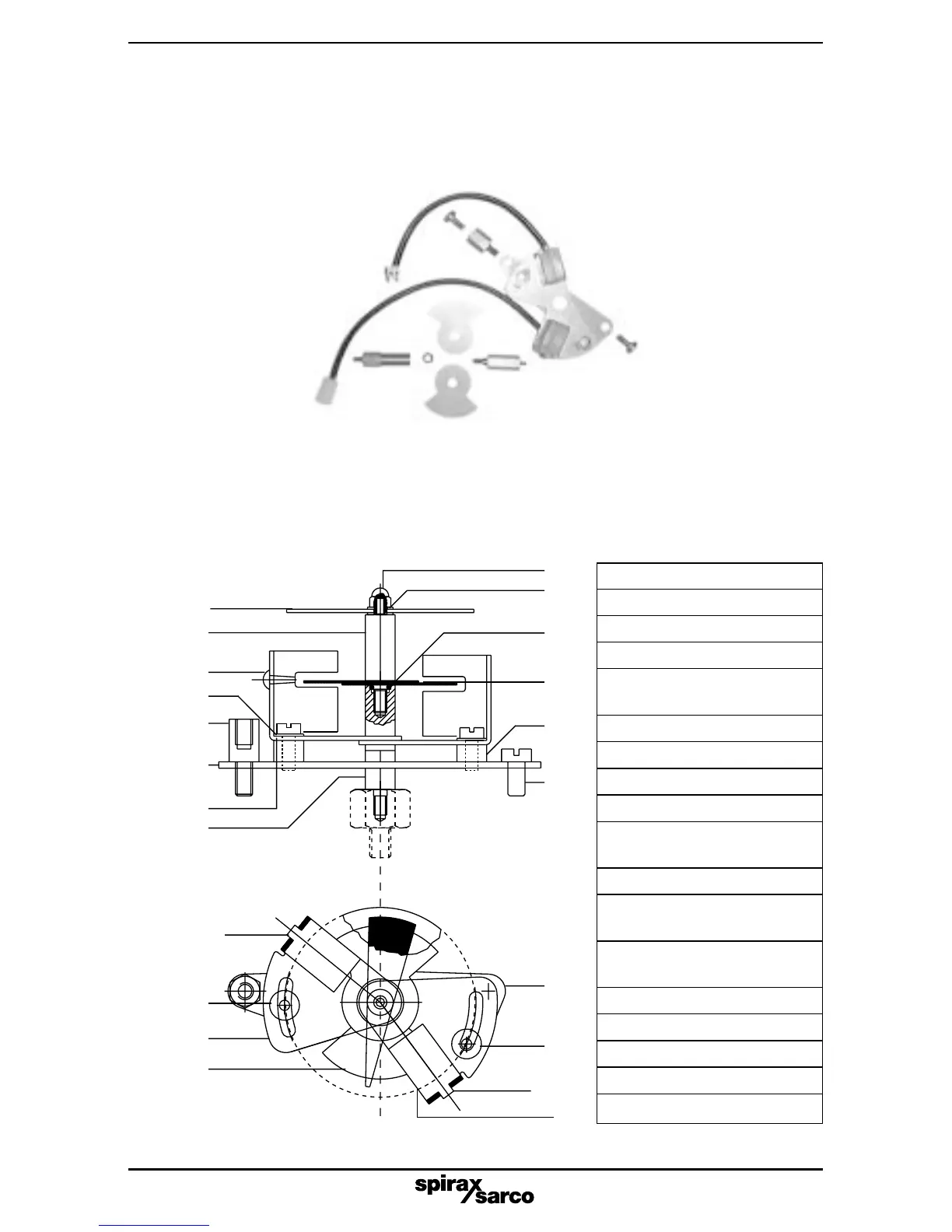
2.3 Fitting Pepperl and Fuchs mechanical proximity switches
2.3.1 Fitting of Pepperl and Fuchs switch assembly. Refer to Fig. 5 for components and
Fig. 6 for general assembly.
Fig. 5 Pepperl and Fuchs switch assembly kit components
No. Description Quantity
1 Support plate 1
2 Spacer 1
3 Spacer 1
4
Adjustment
plate
2
5 Switch sensor 2
6 Switch vane 2
7 Fixings 2
8 Screws (M4 x 8) 1
9
Adjustment
screw
2
10 'O' ring 1
11
Earth adaptor
screw
1
12
Extension
spindle
1
13 Spindle 1
14 Washer 2
15 Domed nut 1
16 Indicator disc 1
17 Washer 2
2.3.2 Prepare the assembly kit by unscrewing the extension spindle (12) and remove the two
switch vanes (6). Remove the spindle (13) ensuring that the 'O' ring (10) remains in place.
16
7
11
1
17
2
13
12
15
14
10
3
8
9
1
PF2
5
6
4
PF1
Fig. 6 General assembly
6
9