IM-P146-01 CMGT Issue 4
9
3
Note: Before actioning any installation observe the 'Safety information' in Section 1.
Referring to the Installation and Maintenance Instructions, name-plate and Technical Information Sheet,
check that the product is suitable for the intended installation:
3.1
Check materials, pressure and temperature and their maximum values. If the maximum operating
limit of the product is lower than that of the system in which it is being fitted, ensure that a safety
device is included in the system to prevent overpressurisation.
3.2
Determine the correct installation situation and the direction of fluid flow.
3.3
Remove protective covers from all connections and protective film from all name-plates, where
appropriate, before installation on steam or other high temperature applications.
3.4
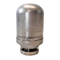
The UFT32 can be installed on any pipeline connector, but must be installed in a horizontal plane
with the ‘TOP’ label facing upwards.
See separate Installation and Maintenance Instructions for Spirax Sarco pipeline connectors
(IM-P128-06, IM-P128-11 and IM-P128-13).
Ensure that both gaskets are clean and undamaged and that the transfer holes are clear. Place
the UFT32 body against the connector gasket face, ensuring that the label 'TOP' is uppermost
and the trap itself is horizontal.
Ensuring the new connector screws supplied with the trap are used, apply a small amount of
anti-seize compound to the threads of the connector screws (3).
Tighten the screws finger tight until the mating gasket faces are in parallel, intimate contact.
Tighten the screws to the recommended torque value (see Table 1).
Open isolation valves slowly until normal operating conditions are achieved.
3.5
Check for leaks.
Note: If the trap is to discharge to atmosphere ensure it is a safe place, the discharging fluid may be at a
temperature of 100 °C (212 °F).
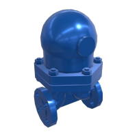
Fig. 4
UFT32 trap unit and gaskets
3. Installation
Table 1 Recommended tightening torques
Item Part
or
mm
N m (lbf ft)
3 Connector screws 9/16" A/F 30 - 35 (22 - 26)
 Loading...