6
• To have the common alarm activate on a dryer fault
condition only, the jumper at JP6 is installed.
NOTE:
Before turning high voltage on to the dryer, an
ohmic test should be performed on the heater elements
to insure they are dry before proceeding with start-up.
This should be done after extended shut downs and long
delays between delivery and start-up. Connect one lead
of a megger to an unpainted surface of the control panel
or dryer frame. Connect the other lead to each phase on
the load side of the contactor. Adjust the megger to the
1500 volt setting. Perform the ohmic test on each zone
of the heaters. A minimum value of 500k ohms must be
obtained.
CAUTION - Failure to ohmic test heaters after ex-
tended periods may cause heater failure.
4.5.1 RS-232 Connections
RS-232 connections can be made at the 3-pin connector
labeled J3 and located at the upper left-handed corner
of the control board. A cable for this connection can be
purchased through your distributor.
4.6 Initial Desiccant Charge
Externally Heated Purge Air dryers use activated alumina
as the desiccant in the dryer towers.
Models 300 through 1050 are shipped with activated alu-
mina (1/8” bead) in the dryer towers. Desiccant is shipped
loose with all other standard models.
All desiccant shipped loose must be added to the
dryer towers before the dryer is put into service
Refer to TABLE 1, DESICCANT REQUIREMENTS for
desiccant type and quantity per tower.
To Add Desiccant
WARNING — The following procedure provides
instructions for adding the initial desiccant to the
towers. If replacing desiccant, refer to the “Proce-
dure for Desiccant Charge Replacement” in the Dryer
Instruction Manual.
1. Verify pressure gauges of both towers indicate 0 psig.
If not, depressurize the towers according to the shut-
down instructions in the Dryer Instruction Manual.
2. Remove the pipe plug or ll port ange cover (where
applicable) from the desiccant ll port at the top of
each tower. Refer to Figures 3 and 3a for the ll port
location.
CAUTION – Pouring desiccant creates a ne dust;
safety goggles, gloves and a dust mask should be
worn by personnel installing desiccant. Refer to the
Material Safety Data Sheet that accompanies desic-
cant shipped loose for more complete information.
CAUTION – Do not tamp the desiccant in the towers.
Tamping damages desiccant and causes dusting.
3. Refer to Table 1 for desiccant quantity per tower.
When using Table 1 you will nd the desiccant quanti-
ties listed in layers. Each layer will vary in depth due
to the type, quantity and purpose of the desiccant.
Layer 1 must be installed rst at the bottom of the
tower followed by layer number 2 etc., until the com-
plete charge of desiccant has been installed.
4. Utilizing an appropriate sized funnel, ll each desic-
cant tower as follows:
a. Install the required quantity of activated alumina
in layer 1 of each tower.
b. Level layer 1 and each subsequent layer of desic-
cant as added to each tower.
c. Finish lling each tower with desiccant until all
desiccant has been installed. LIGHT tapping
on the tower sides with a soft-face mallet should
yield additional free space to allow installation of
all desiccant required. DO NOT TAMP OR RAM
DESICCANT.
5. Clean the ll port closure. Replace the ll plug using
Teon tape or another pipe thread sealant suitable
for compressed air service. Reinstall ll port ange
cover (where applicable) in each desiccant tower.
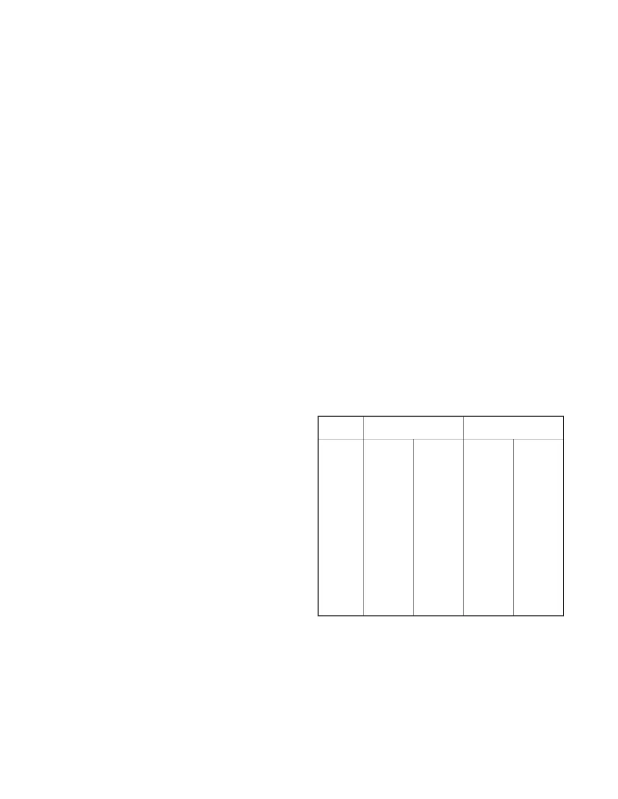
TABLE 1
DESICCANT REQUIREMENTS
(Quantity per Tower)
Model
Layer #1 Layer #2
(lbs.) (p/n) (lbs.) (p/n)
300 210 AA-4 — —
400 354 AA-4 — —
500 354 AA-4 — —
600 453 AA-4 — —
750 590 AA-4 — —
900 590 AA-4 — —
1050 710 AA-4 — —
1300 48 AA-25 876 AA-4
1500 92 AA-25 1167 AA-4
1800 92 AA-25 1167 AA-4
2200 161 AA-25 1706 AA-4
2600 161 AA-25 1706 AA-4
3200 258 AA-25 2119 AA-4
AA = Activated Alumina