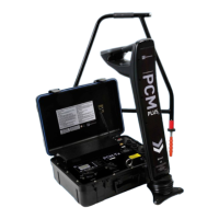
PCM
+
Operation Manual 13
Locate current and 4Hz current measurements can be
taken in the ELF, LF, CPS and 8kHz location frequencies.
On a slope the attachment allows a certain degree of
adjustment to help maintain this position.
Try to atten the ground so that PCM
+
magfoot is parallel
to the pipeline.
Note that positioning the PCM
+
at angles other 90° may
result in inaccurate depth and current measurements.
Note: Accurate PCM
+
results rely on accurate depth
measurement. As magnetic eld distortion is likely at T
intersections, junctions, bends or depth changes of the
pipeline, try to avoid taking PCM
+
measurements above
these points.
4.5 Current Direction
The PCM
+
transmitter is capable of outputting a CD
(current direction) signal and this is available in the
ELCD and LFCD modes. In either of these modes the
transmitter outputs an 8Hz signal which can be used to
provide direction of current owing on the pipeline. This
feature is particularly useful to identify the target pipeline,
which has had the PCM signal applied to it.
When a measurement is taken in either ELCD or LFCD
mode, direction arrows are displayed on the PCM
+
display. When locating and taking measurements on the
target pipeline, by default, the CD arrow will point back
towards the transmitter. On some applications the PCM
+
output signal can leak or couple onto an adjacent pipeline
and in this condition the CD arrow will point away from
the transmitter.
4.6 Mapping Current Measurements
Obtaining and understanding results
A current owing on a buried conductive structure
produces a magnetic eld directly proportional to
the magnitude of the applied current. By resolving
components of the magnetic eld from above surface
the original current can be precisely determined.
At the heart of the PCM
+
system is the current mapping
near DC signal applied by the transmitter. A pipeline’s
electrical characteristics of current attenuation and
distribution at this very low frequency (4Hz) signal are
virtually the same as they are for the Cathodic Protection
current from the rectier.
The PCM
+
Receiver contains a precision; high
performance sensor known as a magnetometer which
remotely detects and measures very low frequency
magnetic elds. Advanced signal processing technology
provides push button current measurement (and direction)
of the near DC (4Hz) signal and a datalogging function
enables graph of current loss against distance to be
plotted after downloading to the PC of PDA.
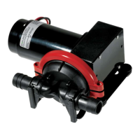
Figure 4.3: Pipeline current flow
Figure 4.4: Pipeline current flow
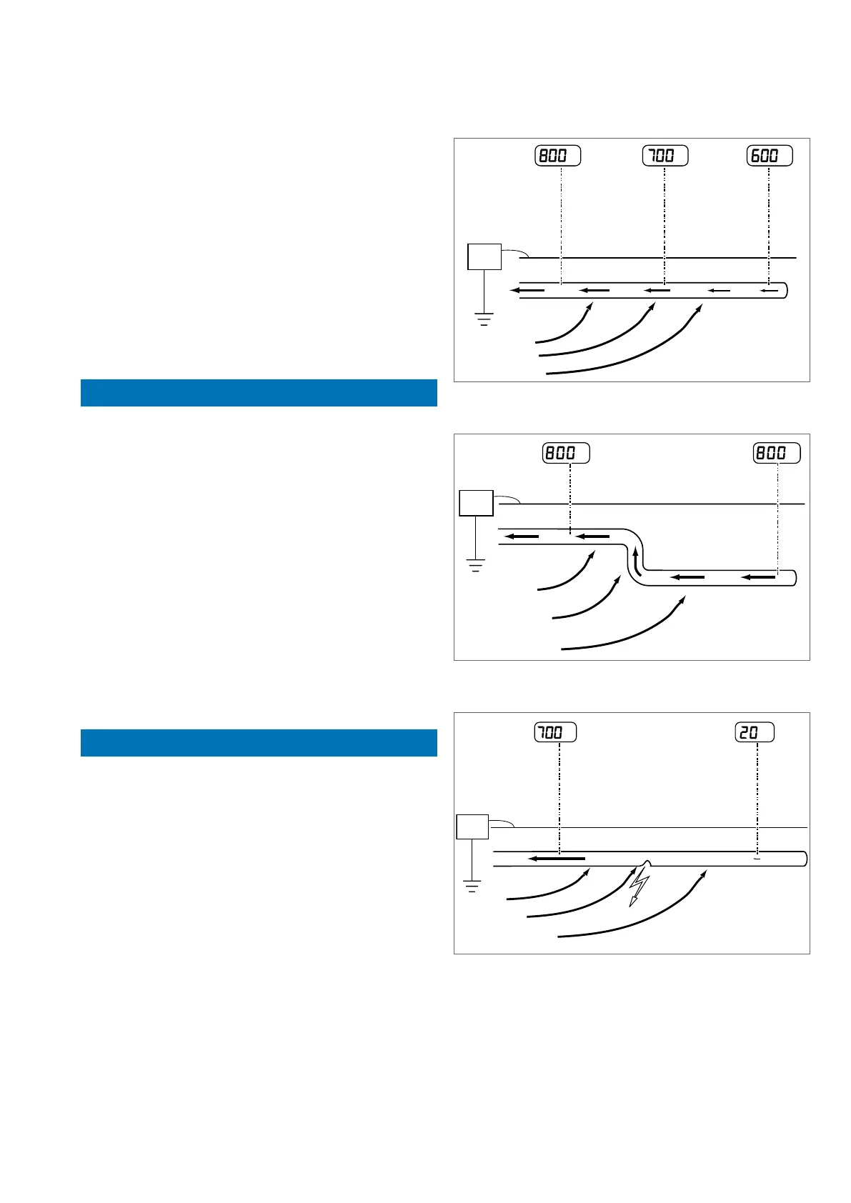
Figure 4.5: Pipeline fault
In all diagrams, the arrows indicate the direction of
current ow to the transmitter.
The PCM
+
Transmitter applies a current to the pipeline
and this current reduces in strength as the distance from
the transmitter increases. The rate of reduction depends
on the condition of the pipe coating, ground resistivity
and pipe electrical resistance.