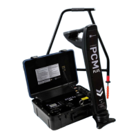
16 PCM
+
Operation Manual
Section 5 – Taking Measurements
This section demonstrates measurement taking and
possible results from surveying various pipe systems.
5.1 Pipelines and Distribution
Systems
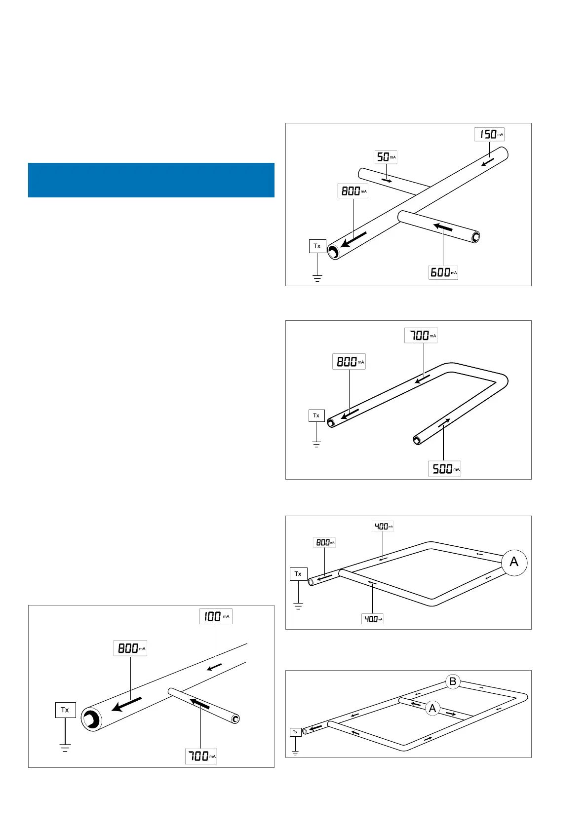
Basic Technique
‘Tie-ins’ and ‘L’
The current will be split between the two lines.
i.e. 800 = 700 + 100
The pipeline with the greatest reading indicates where the
majority of current is owing from and is the direction to
follow in order to locate the fault (short or poor coating).
The current will be split between the three lines.
i.e. 800 = 600 + 150 + 50
The pipeline with the greatest reading indicates where the
majority of current is owing from and is the direction to
follow in order to locate the fault (short or poor coating).
Loops
If the current arrow changes direction it could indicate the
pipe has changed location. Use the PCM
+
in locate mode
to relocate it.
Current flow within a Loop system
If all distances and coatings are equal, and the rate of loss
is constant, the current measured at Point A will be zero.
In practice, with pipes of different ages and coating the
points reading zero (0) could be anywhere. The respective
current readings will indicate the direction to follow.
Figure 5.1: Tie line 1
Figure 5.2: Tie line 2
Figure 5.3: Loop
Figure 5.4: Looped system 1
Figure 5.5: Looped system 2