PCM
+
Operation Manual 19
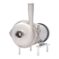
Figure 6.4: Example 2 interpretation
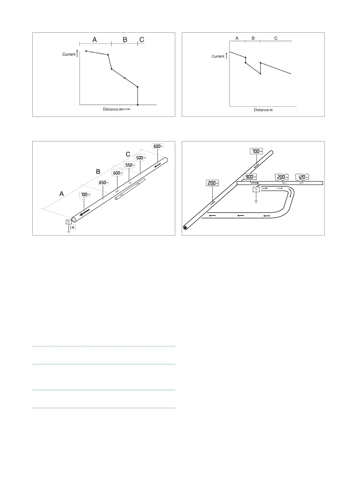
Figure 6.5: Parallel Pipes Example 3
Example
This example (Figure 6.5) demonstrates a typical
application where a short piece of parallel pipeline
interfered with the result.
For ease of explanation the pipeline has been divided into
three parts A, B & C.
In this situation a 1 Amp signal was applied to the new
pipeline and the direction of maximum current ow
followed.
Section A Good Peak and Null locate and a steady rate
of decrease that indicated a good coating.
Section B Poor Peak and Null locate (outside 15cm
(6 inches) requirement) and a signicant
drop in current reading.
Section C Good Peak and Null locate with a rise in
current and then a steady rate of decrease.
Another service was found to be close to the new pipeline
in Section B and had a small amount of current owing
in the opposite direction. This had a cancellation effect,
which caused the current on the new pipeline to fall.
Figure 6.6 illustrates this effect.
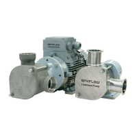
Figure 6.6: Example 3 interpretation
Figure 6.7: Angled Pipes Example 1
Example
This example (Figure 6.7) demonstrates a survey on new
pipeline where the current on one side of the transmitter
owed away from the transmitter.
The PCM
+
Transmitter was connected and a 1 Amp
current selected.
A reading of 900mA was detected on one side with the
arrows pointing towards the transmitter.
The other side gave a poor Peak and Null with the current
pointing away from the transmitter.
Another reading was taken further away from the
transmitter with the same result.
It was found that another service was shorted to the
pipeline as shown and at some stage ran parallel to the
new pipeline. The current on the new pipeline had no
effect as it was so small compared to this other service.
Locating bonding cables between new and old pipelines
by moving PCM
+
Transmitter to both ends of a new
transmission pipeline that had an older discarded pipeline
running parallel and about 3m (10’) away.
The PCM
+
Tx was connected at a rectier and a current
measurement of 800 mA conrmed the direction to follow.