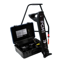
12 PCM
+
Operation Manual
Section 4 – Basic Locating
If the PCM
+
transmitter is connected and switched
on, locate using the ELF or LF frequency modes. If no
transmitter is connected use either 50/60Hz to detect
power or CPS to locate 100/120Hz from CP system.
Switch on the PCM
+
receiver and use the Function key to
select operating frequency to locate the pipeline.
4.1 Pinpointing a Target Line
Pinpointing denes the exact position and direction of
a pipeline after it has been traced and its position is
approximately known. Pinpointing is important as the
depth and current readings are affected by misalignment
errors.
4.2 Peak Procedure
Adjust the PCM
+
Receiver sensitivity to half scale. If the
bar graph is full, press the down arrow; this will reduce
sensitivity and the bar graph to 60%. It may be necessary
to adjust the gain during the procedure to keep the bar
graph on scale.
Hold the detection blade near the ground and
with the blade vertical.
Make traverses from side to side of the pipeline
and dene the point of maximum response.
Turn the Receiver around as if it is a pivot. Stop
at the maximum response and note receiver
direction. Reduce sensitivity if necessary.
Continue to rotate receiver until display shows
zero response; the blade is now parallel with the
pipeline, and this shows the exact direction of the
pipeline. Rotate the receiver through 90 degrees.
The response is now at a maximum.
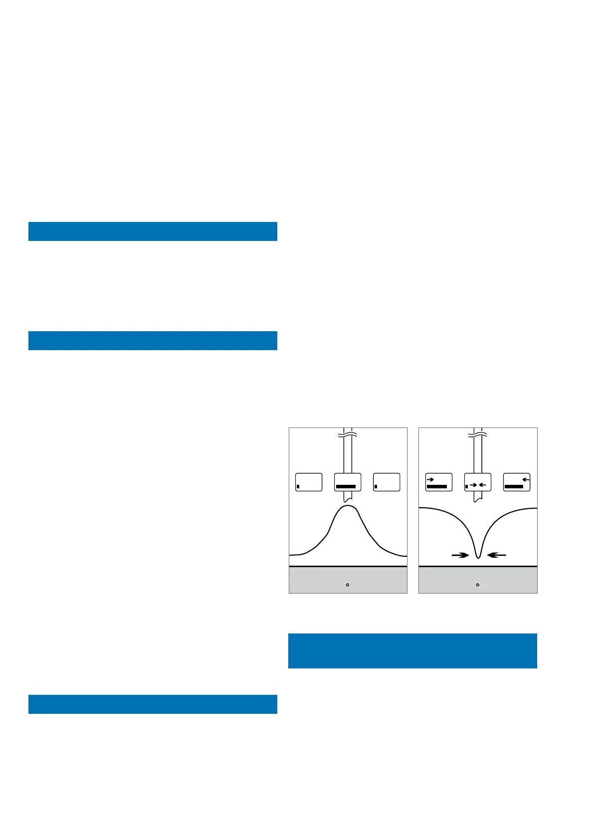
Move the Receiver gently from side to side to
dene the exact position of the peak response.
The detection blade will then be directly over the
pipeline and at right angles to it.
Mark the pipeline position.
4.3 Null Procedure
Follow the procedure for pinpointing with a peak response
and mark the position.
Switch to null response and follow the left/right arrows.
Note the position of the null response over the target.
1.
2.
3.
4.
5.
6.
If the positions of the peak and the null pinpoints
correspond, it can be assumed that the pinpoint is
precise. If the positions do not correspond, the pinpoint
is not precise. Note that both peak and null pinpoints will
show an error to the same side. True position will be close
to peak position.
Accurate PCM
+
results are only obtained when the Peak
and Null positions are within 15cm (6 inches) of each
other.
Effects of interference from parallel pipes and valves on
the Peak and Null positions.
If Peak and Null locates are different by more than 15cm
(6 inches), assume that the magnetic eld is distorted
and take PCM
+
readings at a different position.
When searching for a service, ‘Tie-ins’ or ‘L’ then perform
a box sweep of the area. Walk to the side of the pipe,
turn the gain up until a 50% reading is obtained.
When walking around the box remember to keep the
PCM
+
Receiver in position so that the blade is never in
line with the pipe.
Figure 4.1: Peak mode Figure 4.2: Null mode
4.4 Depth and Current
Measurement
When taking depth and current measurements, it is
important to position the PCM
+
directly above the pipeline
and at 90° to it’s estimated direction.
Note: In Null mode depth, locate current and 4Hz
current measurements are not available.
Pipeline depth measurements can be taken in all of
the location frequencies except 50/60Hz Power
frequency mode.