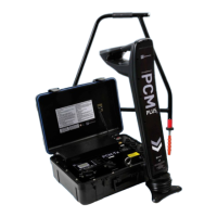
PCM
+
Operation Manual 21
Section 7 – PCM
+
A-Frame
This section provides users with operating
instructions for the PCM
+
accessory A-Frame.
7.1 About the A-Frame
The accessory A-Frame is used with the PCM
+
receiver to
precisely pinpoint coating defects and isolation faults.
The A-Frame spikes need to make good electrical contact
with the ground, preferably with damp, conductive earth.
The PCM
+
receiver display indicates direction to the
fault, using the CD direction arrows, and this makes fault
position easy to locate.
The PCM
+
also displays the dB microvolts reading across
the A-Frame spikes, and this allows a comparison to
be made between different faults to determine the most
severe. This numeric value along with the direction arrows
can be stored in the PCM
+
datalogging facility, recalled,
and uploaded via Bluetooth to a PDA and then later to
your PC or PDA.
7.2 Operation
After obtaining PCM
+
current loss using the 4Hz results,
decide which sections of the pipeline require fault nd
survey.
There are 2 fault nd modes on the PCM
+
receiver, which
can be used with the A-Frame:
ACVG
8KFF
On the PCM
+
receiver ACVG fault nd uses ELCD and
LFCD outputs from the PCM transmitter. 8KFF is used
when using a Radiodetection transmitter such as the
RD4000 T3, RD4000T10 or the RD7K/8K Tx-3 and
Tx-10.
Note: With the Accessory A Frame plugged in, it is not
possible to take PCM
+
Current readings.
Plug the 3 pin connection lead into the A-Frame,
and the multipin connector into the accessory
socket on the front of the PCM
+
Receiver.
Locate the pipeline using any one of the locate
frequencies. Position the A-frame above and in
line with the pipeline, and the spike marked with
green tag away from the transmitter connection
point, red spike tag towards transmitter.
•
•
1.
2.
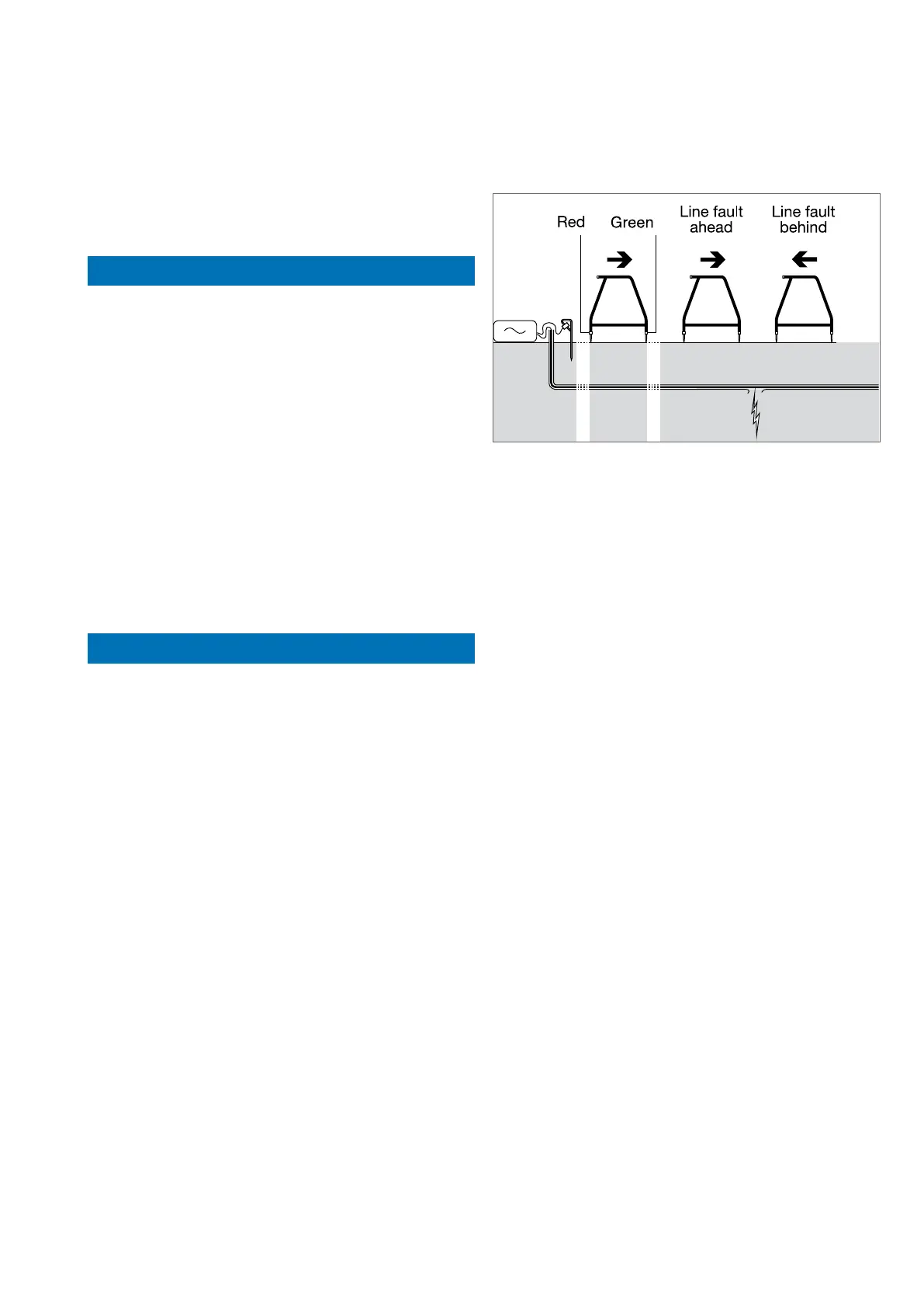
Figure 7.1: A-Frame Fault-Finding
On the PCM
+
receiver select ACVG or 8KFF using
the function key, the A-Frame symbol will appear
on the LCD
Push the A-Frame spikes into the ground to take
a reading. It will then automatically adjust its signal
level and calculate the current direction towards
the fault and the dB microvolt reading. Note that
the gain numbers will ash during calculations.
No user adjustment is necessary.
Display arrows indicate PCM
+
transmitter
current direction through the ground, for user
convenience this is arranged to display direction
to fault. If no arrows are displayed there is unlikely
to be a fault close by, and there is too little current
in the ground to activate the fault direction arrows,
or by chance the A-Frame is directly over a fault.
Make sure that there is good ground contact. Pouring
a small amount of water on a road surface will improve
results.
The display also indicates the dB microvolt reading.
If reading is around 30 or less, there is unlikely to be a
fault nearby.
Move further along the pipeline and make ground
contact with the A-Frame spikes again. When a new
position gives CD arrow indication forwards, and
the next gives CD arrow indication backwards, the
operator has walked over a fault. A numerical dB
microvolt reading of around 60 can be expected.
Move backwards along the pipeline taking tests at
1 meter intervals. See that the numerical dB
microvolt reading value rises, briey falls, and rises
again, before gradually reducing. The CD arrows will
also change direction either side of the fault point.
3.
4.
5.
•
•