Model SR555 Stand-On Scale
Operating and Service Manual - S/N 1800+
Part No. MAN555_060829 Page 4 of 18
SInstruments, Inc., 600 Young Street, Tonawanda, NY 14150
Tel: 716-693-5977 Fax: 716-693-5854 URL: www.srscales.com
email: sri@srinstruments.com Copyright 2006 SInstruments, Inc.
ASSEMBLY
STEP 1: Unpack the scale system and check parts
against the PACKING CHECKLIST. If there are any
missing or damaged parts, please call the service hotline
at 1-800-654-6360.
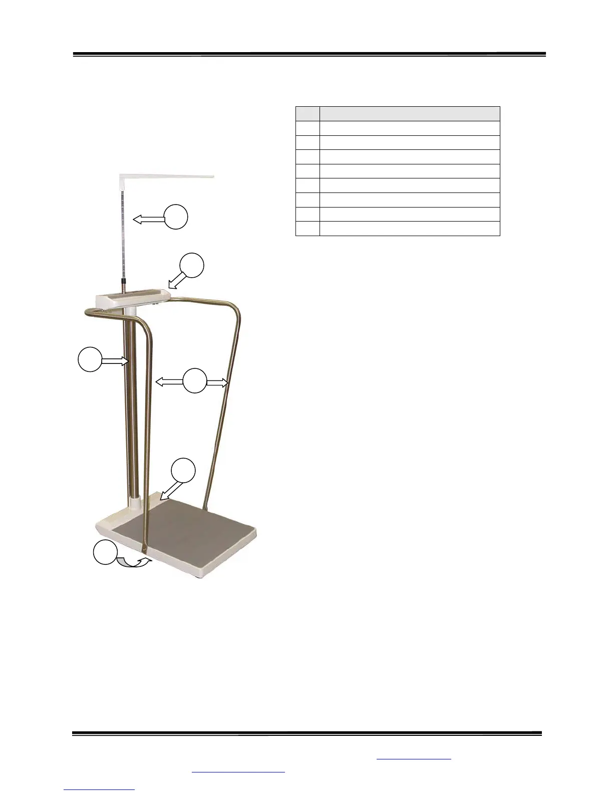
STEP 2: (Figure 1) Verify that the serial number on the
Display Unit (1) matches that on the Base Assembly (2).
STEP 3: Remove the four (4) set screws from Base
Assembly collar and apply a small amount of Loctite
to each. Insert Mast (3) into Base Assembly collar and
seat firmly. Re-install set screws in Base Assembly
collar and tighten securely.
STEP 4: Feed the display cable down through the Mast
and pull out through the Base Assembly.
STEP 5: Remove the set screws from the Display Unit
collar. Set the Display Unit squarely on top of the Mast
with the display label facing the scale platform. Apply a
small amount of Loctite to the four (4) set screws and
reinstall the set screws, tightening securely.
# PART NAME
1
Display Unit
2
Base Assembly
3
Mast
4
Cable Clamp
5
Display Cable Connector
6
Handrails (optional)
7
Height Bar (optional)
8
Battery Compartment
Figure 1: Assembly Diagram
Continued next page
1
7
8
3
6
2