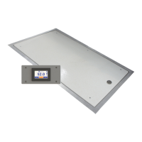
Model SR555 Stand-On Scale
Operating and Service Manual - S/N 1800+
Part No. MAN555_060829 Page 5 of 18
SInstruments, Inc., 600 Young Street, Tonawanda, NY 14150
Tel: 716-693-5977 Fax: 716-693-5854 URL: www.srscales.com
email: sri@srinstruments.com Copyright 2006 SInstruments, Inc.
ASSEMBLY cont’d
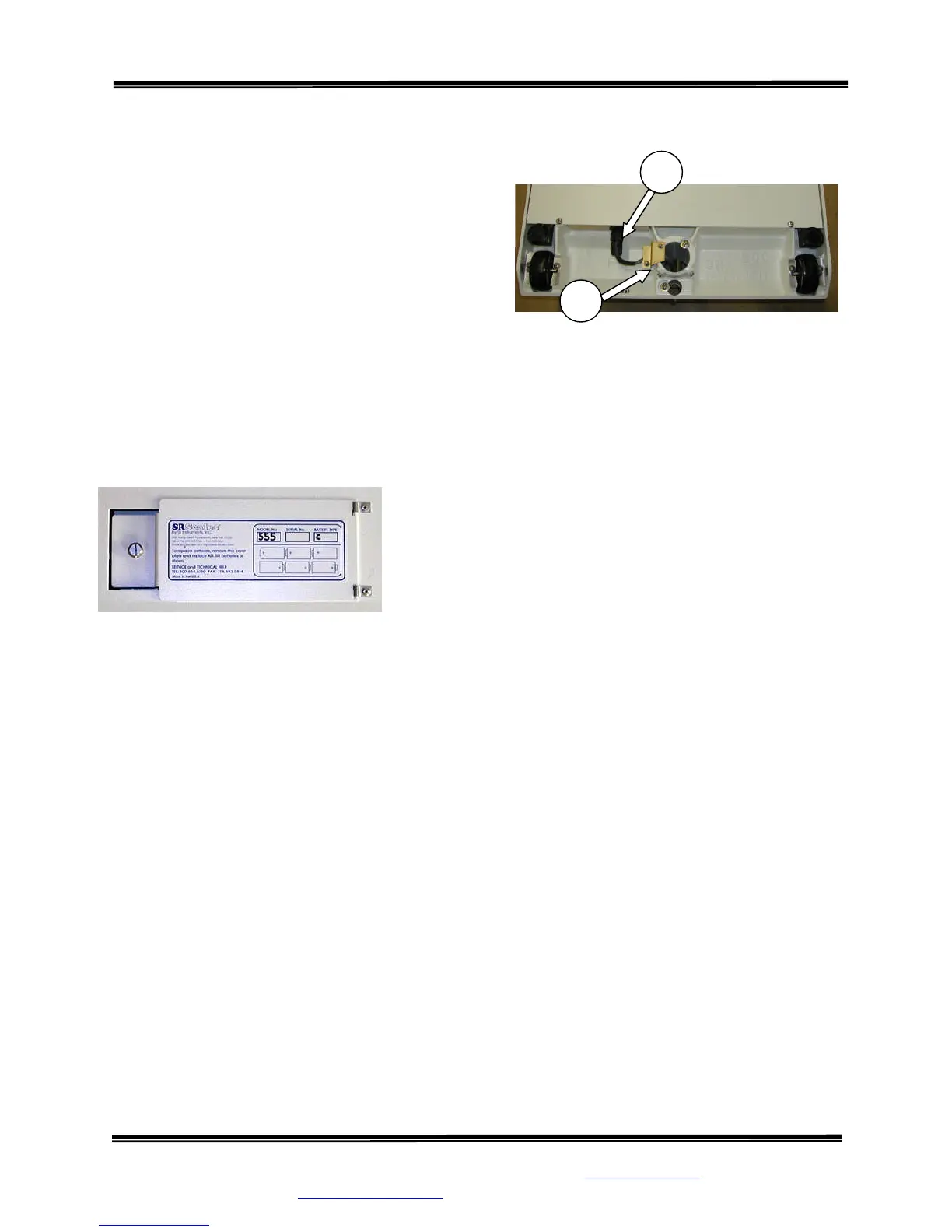
STEP 6: (Figure 2) Lay the system on its side
and remove the Cable Clamp (4) from the Base
Assembly. Attach the Display Cable Connector
(5) to its mate in the Base Assembly.
STEP 7: (Figure 2) IMPORTANT: Reinstall
the Cable Clamp! Set the display cable into the
groove under the Cable Clamp and reinstall the
Cable Clamp, leaving just enough slack to
alleviate any tension on the Display Cable
Connector. Securely tighten the two (2) Cable
Clamp screws. Slide the extra cable back up into
the Mast. Excess cable MUST NOT contact the
floor.
STEP 8: (Figure 3) Open the Battery Compartment cover
and install the six (6) supplied “C” cell batteries as indicated
on the cover diagram. Tightly close the cover.
STEP 9: Return the scale to the upright position.
Figure 2: Cable Clamp, Display Cable, Connector,
and Set Screws
Figure 3: Battery Compartment Diagram
4
5
Continued next page