Model SR555 Stand-On Scale
Operating and Service Manual - S/N 1800+
Part No. MAN555_060829 Page 6 of 18
SInstruments, Inc., 600 Young Street, Tonawanda, NY 14150
Tel: 716-693-5977 Fax: 716-693-5854 URL: www.srscales.com
email: sri@srinstruments.com Copyright 2006 SInstruments, Inc.
ASSEMBLY cont’d
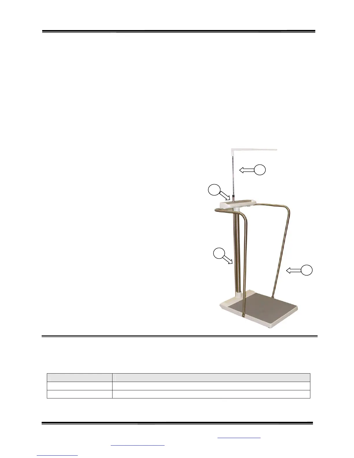
INSTALLING OPTIONAL HANDRAILS
STEP 1: (Figure 4) Attach top of each of the Handrails (6) to the bottom right and left of the
Display Unit (1) with the two (2) screws and two (2) split-lock washers on each side and slightly
tighten. (Do not tighten all of the way.)
STEP 2: Attach the bottom of the Handrails to the right and left side of the Base Assembly
using one (1) screw and one (1) split-lock washer for each handrail. Tighten all six (6) screws
securely.
INSTALLING OPTIONAL HEIGHT BAR
STEP 1: (Figure 4) Remove the set screw on the back
of the Display Unit (1) and in the Base Assembly (2).
STEP 2: Slide the Height Bar (7) down through the
hole in the Display Unit and seat firmly into the Base
Assembly. Apply a small amount of Loctite to the two
(2) set screws and reinstall, tightening securely.
REPLACEMENT PARTS and ACCESSORIES
Figure 4: Handrail/Height Bar Diagram
Part # Description
SR3070 Handrail Set with assembly hardware
SR3086 Height Bar: Extends from 43 in to 79 in (109 cm to 201 cm)
1
2