NEW
NEW
NEW
30
SRAM P5 CARGO
TECHNICAL DATA / ASSEMBLY REQUIREMENTS
Technical Manual 2006
SRAM P5 CARGO
ASSEMBLY
Spoke lengths are approximate values. They must be checked through lacing attempts
and adjusted accordingly.
Tire Size Cross Length MH 5215 Length MH 5225
47–406 20" x 1.75 x 2 3 x 181 mm 179 mm
37–490 22" x 1
3
/
8
3 x 225 mm 222 mm
47–507 24" x 1.75 x 2 3 x 232 mm 229 mm
37–540 24" x 1
3
/
8
3 x 251 mm 248 mm
47–559 26" x 1.75 x 2 3 x 259 mm 256 mm
37–590 26" x 1
3
/
8
3 x 275 mm 272 mm
47–622 28" x 1.75 3 x 289 mm 286 mm
37–622 28"x1
3
/
8
x 1
5
/
8
3 x 289 mm 286 mm
28–622 28"x1
1
/
8
3 x 289 mm 286 mm
32–622 28"x1
5
/
8
x 1
1
/
4
3 x 289 mm 286 mm
28–630 27"x1
1
/
4
fifty 3 x 294 mm 291 mm
32–630 27" x 1
1
/
4
3 x 294 mm 291 mm
Spoke length table:
ASSEMBLY HUB
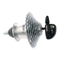
• Lace the wheel as normal. See spoke
length table.
• Place the dust cap (1, Fig. 1) and
sprocket (2) on the driver.
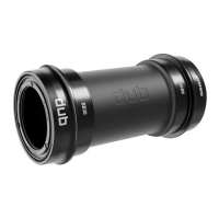
• Push sprocket circlip (3, Fig. 2) onto the
cone of tool sleeve (4). Place tool sleeve
with large diameter on the driver.
• Push the spring end of sliding sleeve (5)
of the tool over the tool sleeve. Thrust
sliding sleeve in direction (6), this forces
circlip into the recess of the driver.
• Remove tool and check that the circlip is
seated correctly.
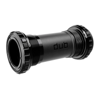
• Turn dust cap (7, Fig. 3) until the three
lugs (8) are between the three beads (9)
on the sprocket (10).
• Position dust cap and push towards
sprocket until it is felt to lock into place.
• Placing the wheel in the rear frame.
• Fit new retaining washer (3,5 mm thick)
on left axle end (1, Fig. 4). The serrations
must bear against the dropout and the
lug must engage in the dropout slot.
Advice:
For bicycles with chain tensioner use
previous retaining washers (2 pieces,
2 mm thick) – see Tech. Manual 2005.
• On the sprocket side fit the protective
bracket (1, Fig. 5) directly below the
axle nut. Tightening torque on axle nuts
30 – 40 Nm (266 – 350 in.lbs.).
• Mount the brake lever using a suitable
frame clamp (2, Fig. 4 resp. Fig. 10).
Caution:
Mount the brake lever between the two
straps of the frame clamp.
The clamp must be seated on the frame
without play.
Use a self-locking nut! Tightening
torque: 2 – 3 Nm (18 – 27 in.lbs.).
SRAM Grip 5
Shifter Type Twist Shifter
Cable Length 1450 mm
❘
1550mm
❘
1650mm
❘
1750mm
❘
1850mm
❘
1950mm
❘
2150mm
❘
2350mm
Gear Indication Window
Clamping Diameter 22.3 mm
Handlebar, Straight Area
Minimum length for shifter = 150mm
Weight 89g
Housing Glass filled PA
Grip PP
Grip Cover
Thermoplastic elastomer, Overmolded
Clamping Collar Aluminum
Design
S
H
I
F
T
E
R
S
3
1
2
4
10
9
8
7
12
1
2
45
6
3
Mounting Tool
Part No. 0582 104 000