31
SRAM P5 CARGO
ASSEMBLY
Technical Manual 2006
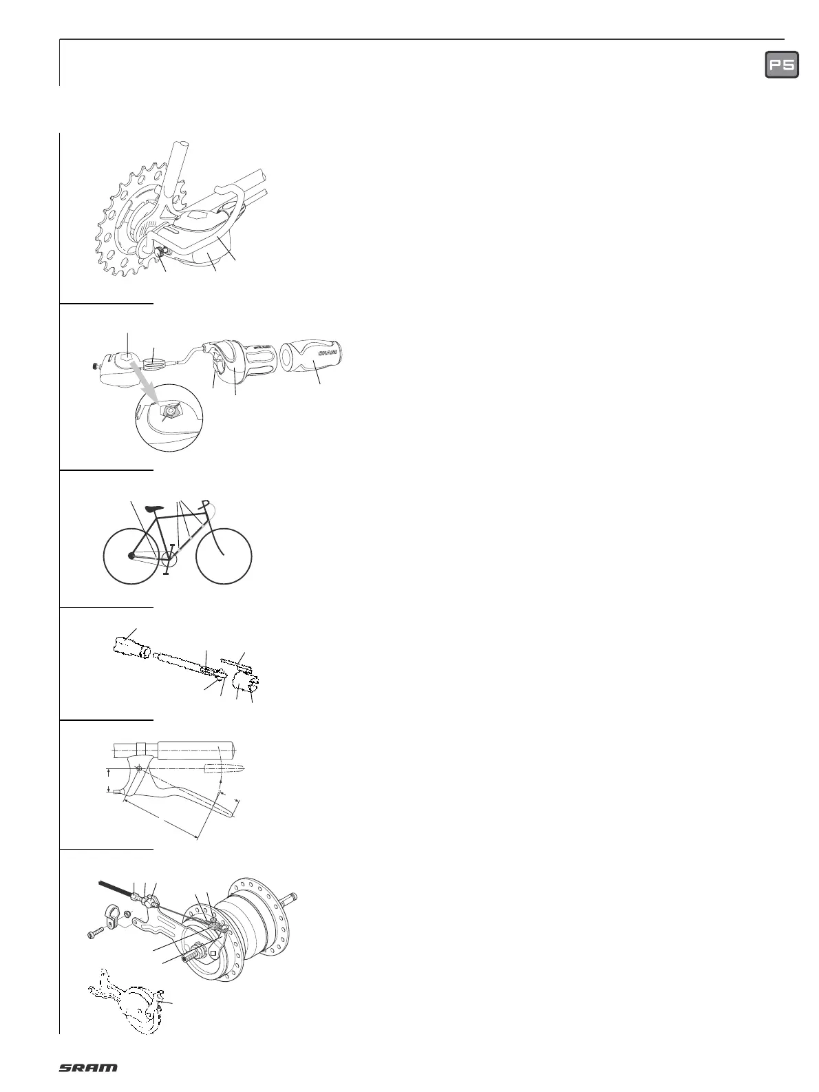
Advice:
• If a different protective bracket (1, Fig. 5)
is used the thickness of the attachment
plate must be max. 3 mm.
• Do not use additional washers.
• At least the beginning of the axle thread
must be visible in front of the axle nut.
Caution:
Check that all the brake system
components are functioning properly!
ASSEMBLY SHIFTER
Advice:
• When choosing cable housing lengths,
be sure to allow enough housing for an
extreme turn of the handlebars in both
directions.
• Note also, that different stem lengths
and handlebar positions effects cable
housing length.
• Slide shifter (1, Fig. 6) onto handlebar.
• Mount fixed grip (2) onto end of handlebar.
• Slide shifter against fixed grip, adjust
shifter on handlebar and tighten with
bolt (3) with a torque of 1.5 Nm (13 in.lbs.).
Caution:
• Never use lubricants or solvents to
install fixed grips.
Fixed grips provide an axial safety
function. For this reason, they should be
mounted in such a way as to make sure
they do not slip off handlebar.
• Check that the shifter and brake lever
function properly and are unobstructed
(realign if necessary).
• Never ride without the fixed grips. The
turning grip may loosen from housing
and slip off handlebar – this can result
in severe injury or death.
• When fitting the cable avoid small radius.
Attach the cable 3 times to the down
tube (1, Fig. 7).
• Last attachment point is on the lower
rear wheel fork (2, Fig. 7) immediately
behind the chain wheel.
Cable housing must be movable inside
attachment.
INSTALLING CLICKBOX
• Insert shift rod (1, Fig. 8) in shift tube (2)
(oil parts lightly) and then push into axle
bore as far as the stop. If the shifting rod
is sticking up out of the axle end: apply
slight pressure on the shift rod with its
threaded section and screw inwards in
a clockwise direction until it can again
be moved axially (valid for older hub
versions). Turn slot (6) in shift tube to a
position where it is easily visible.
• Push locating sleeve (3) with guiding rib
(4) to the front onto the hub axle – making
sure that the internal lug (5) is guided in
the slot (6) of the shift tube until it can be
felt – and heard – to engage.
• Turn locating sleeve on the axle until the
guiding rib (4) is facing roughly upwards.
• Place shifter in gear position “2“.
• Push on Clickbox (2, Fig. 5) to the stop on
the hub axle. The guiding rib (4, Fig. 8) of
the locating sleeve thereby engages in
the slot on the housing. In the end position
tighten up the knurled bolt (3, Fig. 5) by
hand (0.3 Nm / 2.7 in.lbs.).
ADJUSTMENT
• Be sure to reset rotational shifter from
4th to 3rd gear.
• Match up the marks in the Clickbox
viewing window (4, Fig. 6) by turning
the adjusting screw (5).
CONNECTING DRUM BRAKE
Caution:
Only use brake levers with a cable
moving distance of at least 15 mm and a
leverage of “i“ = 3.8 – 4.2 (Fig. 9).
• Fit cable stop (1, Fig. 10) with adjusting
bolt (2) and nut (3) and insert into the slot
on the brake anchor plate.
• Turn adjusting bolt down by approx.
2
/
3
and route the brake cable from the
brake handle.
• Push lower brake cable end through
adjusting bolt (2) and insert lower cable
housing end into adjusting bolt.
• Thread brake cable end (4) into
fork unit (5).
• Tighten screw (6) slightly.
• Attach fork unit to brake lever (7).
• Pull brake cable end taut with pliers
so that fork unit can still be attached and
removed (important for changing wheel).
• Tighten screw (6).
Caution:
For NL version drum brake hub with
special lever (8), only use original NL
brake cable (fork unit (5) is not suitable).
ADJUSTMENT DRUM BRAKE
• Unscrew adjusting screw (2, Fig. 10)
until the brake pads drag lightly.
• Actuate the hand brake lever forcefully
several times and then, if necessary,
turn the adjusting screw further in just
until the wheel starts spinning freely.
• Lock hex nut (3).
Caution:
Check that all the brake system
components are functioning properly!
CARGO
CARGO
7
5
6
8
9
3
2
1
8
5
7
6
4
132
10
a
i =
l
—
a
25
l
7
6
4
5
2
1
3
1
2
1
4
5
2
3
 Loading...