NEW
NEW
NEW
32
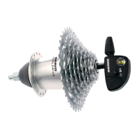
SRAM P5 CARGO
MAINTENANCE
Technical Manual 2006
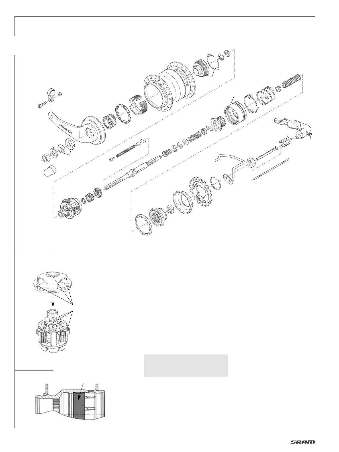
REMOVE WHEEL
• Place shifter in gear position “2“.
• Loosen the knurled screw (41, Fig. 1) and
pull the Clickbox off the axle.
• Disengage the red location sleeve (40)
and pull it off.
• Remove shift rod (39) and shift tube (38)
out of the axle bore.
• Remove wheel.
DISMANTLING HUB
see Fig. 1
• Remove circlip (36), sprocket (35) and
dust cap (34).
• Clamp hub with sprocket side facing
downwards with the two axle flats.
• Unscrew both locknuts (1).
• While turning clockwise, remove lever
cone (2) with friction spring (3) and ball
retainer (4).
• Take out 3 brake segments (5).
• Withdraw hub sleeve (6) upwards.
• Remove brake cone (7).
• Remove retaining washer (8), thrust
washer (9).
• Remove planetary gear carrier (10) and
thrust washer (11).
• Clamp other axle end.
• Unscrew fixed cone (33).
• Remove driver (32), compression spring
(30), large compression spring (28) and ball
retainer (31).
• Withdraw gear ring (27) and coupling
gear (26) and then remove cover (29)
from the coupling gear.
• Take out thrust block (25), (to do this
compress the spring). Remove spring
(23) and the two covers (24/22).
• Dismantle retaining washer (21), washer
(20), conical compression spring (19),
and the large sun gear (13). Clamp other
axle end (thrust block visible).
• Unscrew grub screw (15) – Dismantle
spring (16), guide bolt (17) and thrust
block (18).
• Remove small sun sun gear (12).
REASSEMBLY HUB
see Fig. 1
Lubrication see “
MAINTENANCE/
LUBRICATION
“.
• Clamp axle with internal thread up-
wards.
• Position small sun gear (12) with crown
gears to the front.
• Position thrust block (18) in the slotted
hole (is laterally guided when the sun
gear is screwed in).
1
1
2
3
4
5
6
7
8
9
14
15
16
18
19
20
21
22
23
13
10
11
12
28
29
30
40
39
38
37
35
36
34
33
32
31
24
25
26
27
17
X
2
3
SRAM P5 mounting aid
Part No. 65 0524 300 000
41
 Loading...