Technical Manual 2006
39
SRAM T3
ASSEMBLY
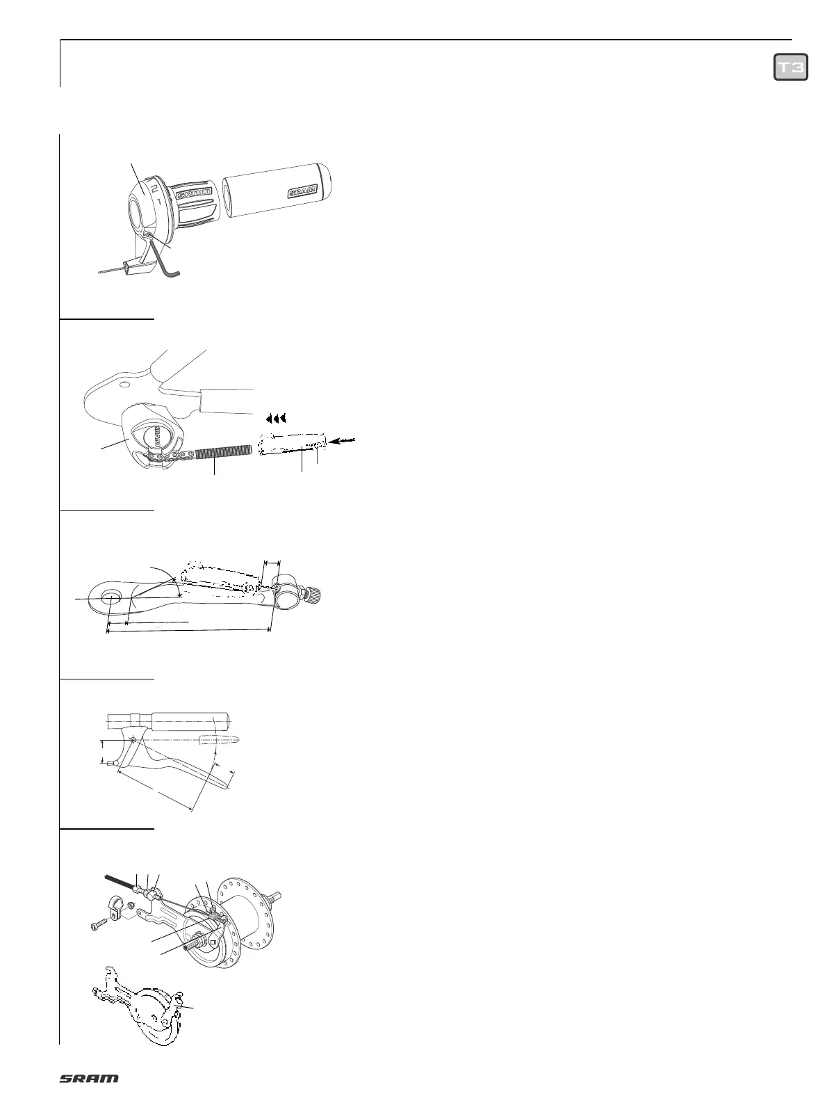
ASSEMBLY SHIFTER
• Slide shifter (1, Fig. 7) onto handlebar.
• Mount fixed grip (2) onto end
of handlebar.
• Without applying pressure, slide shifter
against fixed grip, adjust shifter on
handlebar and tighten with bolt (3). Allen
key 2.5 mm, torque 1,7 Nm (15 in.lbs.)
• Not recommended for use on thin walled
aluminum handlebars such as Hyperlite
©
type handlebars.
Caution:
• Never use lubricants or solvents to
install fixed grips.
Fixed grips provide an axial safety
function. For this reason, they should be
mounted in such a way as to make sure
they do not slip off handlebar.
• Check that the shifter and brake lever
function properly and are unobstructed
(realign if necessary).
• Never ride without the fixed grips. The
turning grip may loosen from housing
and slip off handlebar – this can result
in severe injury or death.
INSTALLING CABLE
• When fitting the cable avoid small radius.
Use only compressionless cable housings
with resin liner inside and capped.
• Screw the cable stop clamp and cable
pully clamp on the down tube or seat tube.
• Secure the lubricated shift cable at
equidistant intervals on the frame
(in case of continuous cable housing).
Advice:
To avoid malfunction the cable frictional
force must not exceed 6 N (1.4 lbs.).
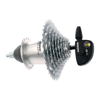
• Feed the shifter cable into the locating
sleeve (5, Fig. 8), fix at the appropriate
length (cable stop bracket: see Fig. 9)
using the clamping bolt (1).
Allan key 2.5 mm, tightening torque
1.5 Nm (13 in.lbs.). Shorten any cable
which is sticking out.
• Connect to the hub: push locating sleeve
(2, Fig. 8) loosely onto small pull rod (3).
ADJUSTMENT
• Place the shifter in gear position "3".
Move the crank to check that the gear
is engaged.
• To make the adjustment, the cable must
be taut in third gear to be able to transfer
a shift movement directly to the hub.
• Push locating sleeve (2, Fig. 8) onto the
small pull rod (3) until the control cable
is taut. Make sure that you don’t pull the
indicator chain out of the deflection
pulley (4).
Check:
• Place shifter in gear position "1" while
moving the crank.
• Setting too loose: In gear position "1" the
tension chain can be pulled out of the
deflection pulley by hand.
• Setting too tight: It is difficult to place
the shift lever in gear position "1".
• If required, readjust the shift mechanism
(in third gear).
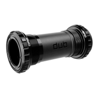
CONNECTING DRUM BRAKE
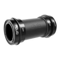
Caution:
Only use brake levers with a cable
moving distance of at least 15 mm and a
leverage of “i“ = 3.8 – 4.2 (Fig. 10).
• Fit cable stop (1, Fig. 11) with adjusting
bolt (2) and nut (3) and insert into the slot
on the brake anchor plate.
• Turn adjusting bolt down by approx.
2
/
3
and route the brake cable from the
brake handle.
• Push lower brake cable end through
adjusting bolt (2) and insert lower cable
housing end into adjusting bolt.
• Thread brake cable end (4) into
fork unit (5).
• Tighten screw (6) slightly.
• Attach fork unit to brake lever (7).
• Pull brake cable end taut with pliers
so that fork unit can still be attached and
removed (important for changing wheel).
• Tighten screw (6).
Caution:
For NL version drum brake hub with
special lever (8), only use original NL
brake cable (fork unit (5) is not suitable).
ADJUSTMENT DRUM BRAKE
• Unscrew adjusting screw (2, Fig. 11)
until the brake pads drag lightly.
• Actuate the hand brake lever forcefully
several times and then, if necessary,
turn the adjusting screw further in just
until the wheel starts spinning freely.
• Lock hex nut (3).
Caution:
Check that all the brake system
components are functioning properly!
10
7
8
11
9
2
1
3
min.
13 mm
min. 90 mm
4
5
min. 12 mm
max. 30°
1
2
3
2.5 mm
1.7 Nm
15 in.lbs.
8
5
7
6
4
132
a
i =
l
—
a
25
l