56
i-BRAKE AND COMPATIBLE HUBS
ASSEMBLY
Technical Manual 2006
ASSEMBLY
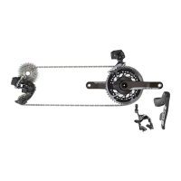
• Lace the wheel as normal. 3-cross only.
Caution:
• Plane faces of brake drum and hub must
be clean and free from oily and greasy
substances.
• Internal area of the brake drum and
brake lining material must be free of
dirt and oil or other substances contain-
ing grease. Danger of accident!
• Slide brake drum (1, Fig. 1) onto centering
seat (2) and fasten crosswise with
appropriate four cylinder head screws (3),
(or four countersunk screws for version
DualDrive). Torx T25, tightening torque
5.5 – 6 Nm (49 – 53 in.lbs.).
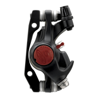
• Slide brake anchor plate (4, Fig. 2) onto
centering seat (5) without tilting it.
Front hubs:
• Apply steel washer (6, Fig. 2) and lock
nut (7), minted side outwards.
Wrench 15 mm, tightening torque
15 – 20 Nm (133 – 177 in.lbs.).
Gear hubs:
• Apply steel/resin washer (6, Fig. 2).
Lock nut (7) must not be used.
Front hubs and Gear hubs:
Advice:
The wheel must turn freely.
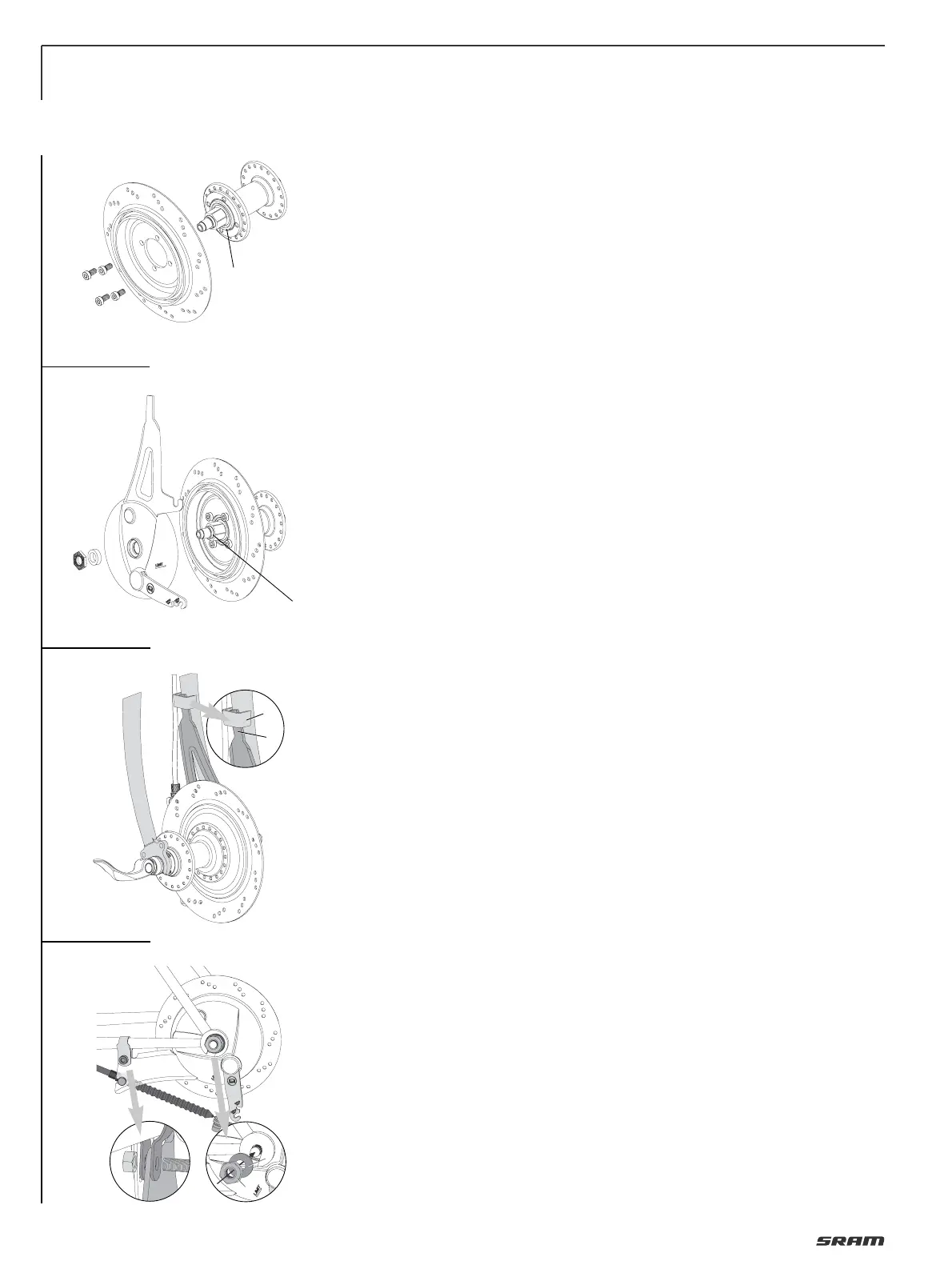
• Placing the wheel in fork ends.
Guide the top end of brake anchor plate
into the brazing part of the front fork
resp. fit frame clamp to fasten the brake
anchor plate at rear fork.
Caution:
Mount the brake anchor plate between
the two straps of the frame clamp (Fig. 4).
The clamp must be seated on the rear
fork with no play.
Use a self-locking nut! Hex screw,
property class 8.8.
Tightening torque: 7– 8 Nm (62–70 in.lbs.).
Fastening wheel / solid axle:
• Fit washers resp. retaining washers (3,
Fig. 4) to the axle ends.
• Tighten up axle nuts, torque 30 – 40 Nm
(270 – 350 in.lbs.).
Fastening wheel / quick release (Fig. 5):
• Only use quick release devices with the
correct length.
• Position quick release opposite to the
brake.
• Turn release lever (8) outwards until it
is at least at a right angle to the bike
(position “OPEN“).
• Tighten adjusting nut (9) as much as
possible by hand.
• Turn release lever (8) to the “closed“
position (10) (the word “CLOSE” is visible
from the outside).
After closure, the release lever should
be parallel to the fork. If the release
lever can be closed relatively easily,
the tension force is inadequate.
In this case, open release lever again,
tighten adjusting nut (9) slightly and
close release lever again.
If considerable force is required to
close the lever, open the lever again,
undo the adjusting nut slightly and
close lever again.
Warning:
• Do not tighten wheel by turning the
quick release lever clockwise (Fig. 6)!
• Only use hand force.
• By incorrectly mounting the skewer or
the wheel in the dropout, or by wrongly
adjusting the closing force, the wheel
may come loose and fall off during
the ride. This may lead to severe rider
injury or death.
3
1
2
4
1
7
6
4
5
2
3
2
1
4
3
 Loading...