58
i-BRAKE AND COMPATIBLE HUBS
MAINTENANCE
Technical Manual 2006
1
2
3
2
1
4
4
3
3
3
1
2
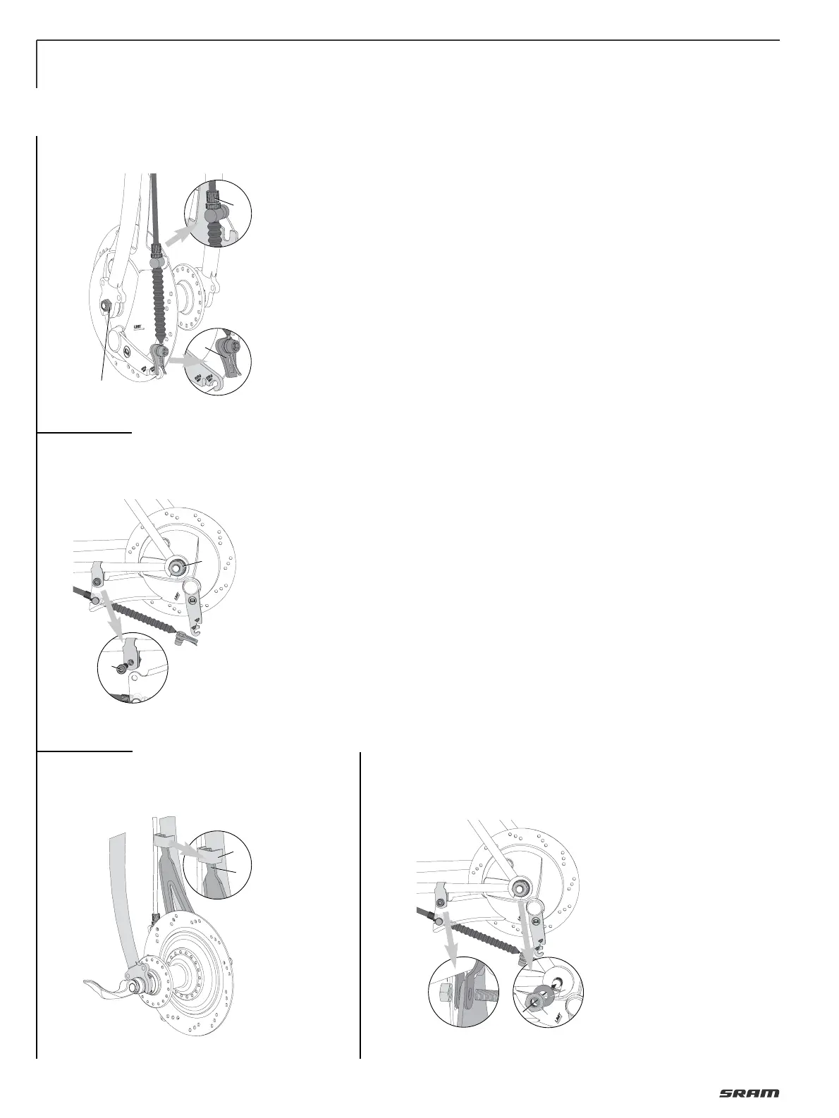
REMOVING THE WHEEL
Caution:
After cycling, the brake and hub should
not be touched. Danger of getting burns!
• Detach the link (1, Fig. 1) on the brake
lever (if necessary, screw the adjust-
ment screw (2) in somewhat until the link
can be detached).
• Grab the adjustment screw (2) and
remove the entire brake cable unit from
the brake anchor plate.
• Rear wheel only: Remove the screw (4,
Fig. 2) on the frame clamp.
• Attachment using axle nuts:
To remove the wheel, remove both axle
nuts (3).
• Attachment using quick-release:
To remove the wheel, open the quick-
release lever.
MOUNTING THE WHEEL
• Placing the wheel in fork ends.
Front wheel:
Guide the top end of the brake anchor
plate (1, Fig. 3) into the brazing part of the
front fork (2).
Attaching a wheel with axle nuts:
Front and rear wheel:
• Slide the washers (3, Fig. 4) onto the ends
of the axles.
• Mount the axle nuts (4) and tighten
them with a torque of 30 – 40 Nm
(270 – 350 in.lbs.).
Rear wheel:
Before tightening the axle nuts attach
the brake anchor plate to the frame using
a suitable frame clamp.
Caution:
Mount the brake anchor plate between
the two straps of the frame clamp (Fig. 4).
The frame clamp must be seated on the
rear fork with no play. Use a self-locking
nut! Screw M6, property class 8.8.
Torque: 7 – 8 Nm (62 – 70 in.lbs.).
4
 Loading...