59
i-BRAKE AND COMPATIBLE HUBS
MAINTENANCE
Technical Manual 2006
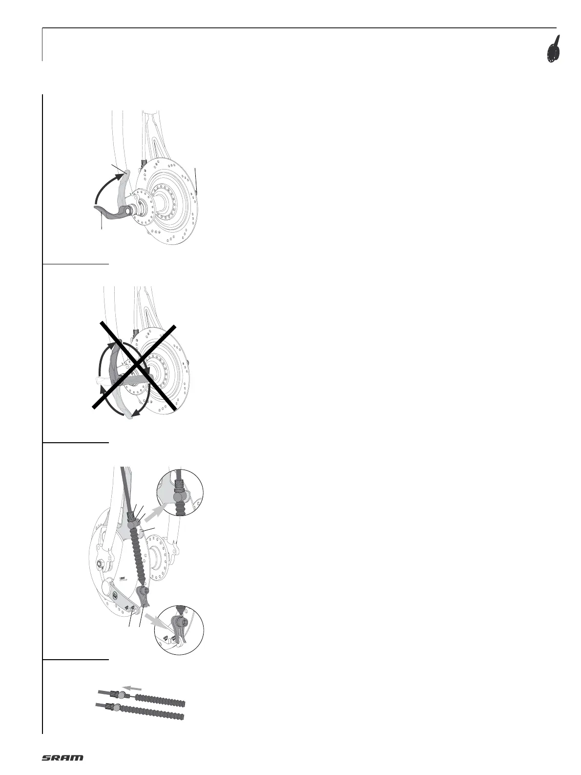
Attaching a wheel with quick release:
• Only use quick release devices with the
correct length.
• Position quick release lever
opposite to the brake.
• Turn release lever (5, Fig. 5) outwards
until it is at a right angle to the bike
(position „OPEN“).
• Tighten adjusting nut (6) as much as
possible by hand.
• Turn release lever to the closed position (7)
(the word “CLOSE” is visible from the
outside).
After closure, the release lever should
be parallel to the fork. If the release
lever can be closed relatively easily, the
tension force is inadequate.
In this case, open release lever again,
tighten adjusting nut (6) slightly and
close release lever again.
If considerable force is required to close
the lever, open the lever again, undo the
adjusting nut slightly and close lever
again.
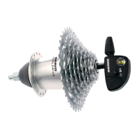
Caution:
• Do not tighten the wheel by turning the
release lever clockwise (Fig. 6).
• Only use hand force.
• By incorrectly mounting the skewer or
the wheel in the dropout, or by wrongly
adjusting the closing force, the wheel
may come loose and fall off during the
ride. This may lead to severe rider in-
jury or death.
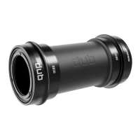
CONNECTING THE BRAKE
• Fit cable stop (1, Fig. 7) with adjusting
bolt (2) and nut (3) and insert into the
slot (4) the brake anchor plate.
• Attach link (5) to brake lever (6). Use
outer standard position “125 kg” (overall
weight).
Put the link in the position first that is
closest to the total weight of the bicycle
with cyclist and baggage.
Positioning of link can be changed to
personal preferences, but we advise to
use according to weight.
Make sure you use the same position af-
ter changing the wheel.
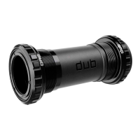
• Attach the bellows to the adjustment
screw (Fig. 8).
• Check the brake adjusting.
See “ADJUSTING THE BRAKE“.
Caution:
Check whether the brake functions
correctly.
6
5
7
2
4
5
6
1
3
closed
open
5
6
7
8