5
DUALDRIVE
TECHNICAL DATA / ASSEMBLY REQUIREMENTS
Technical Manual 2006
CABLE HOUSING
• Use only new high quality cable and
com-pressionless cable housing with
end caps.
• When choosing cable housing lengths,
be sure to allow enough housing for an
extreme turn of the handlebars in both
directions.
• Note also, that different stem lengths
and cable stop positions effects cable
housing length.
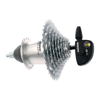
DROPOUT
Only flat and no off-set versions.
Dropout thickness: 7 – 8 mm.
Vertical or horizontal dropout slot.
Dropouts must be parallel.
Dropout dimensions: see Fig. 2 and 3.
CRANKSET
Bicycle without chain case:
Use a chain guard disc (at the outer
surface of chainring, material no resin)
Use only standard chainring version (non-
shifting teeth).
Chainline
DualDrive 27 / 24: 45 mm
Ask for recommended DualDrive-cranks at:
Truvativ
http://www.truvativ.com
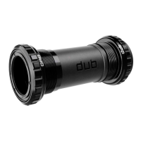
CHAIN GUIDE FORK
It prevents chain from jumping off front
chainring, is bolted inside the chain
case (1, Fig. 4).
HANDLEBAR
Diameter: 22.3 mm.
Minimum length of straight area for shifter:
150 mm.
Check the compatibility of intended
handlebars and brake levers.
L
28
30
X
6–10
7.5–10
A
25˚–30˚
25˚–30˚
R1
8.5 max
8.5 max
R2
11.5–13.5
11.5–13.5
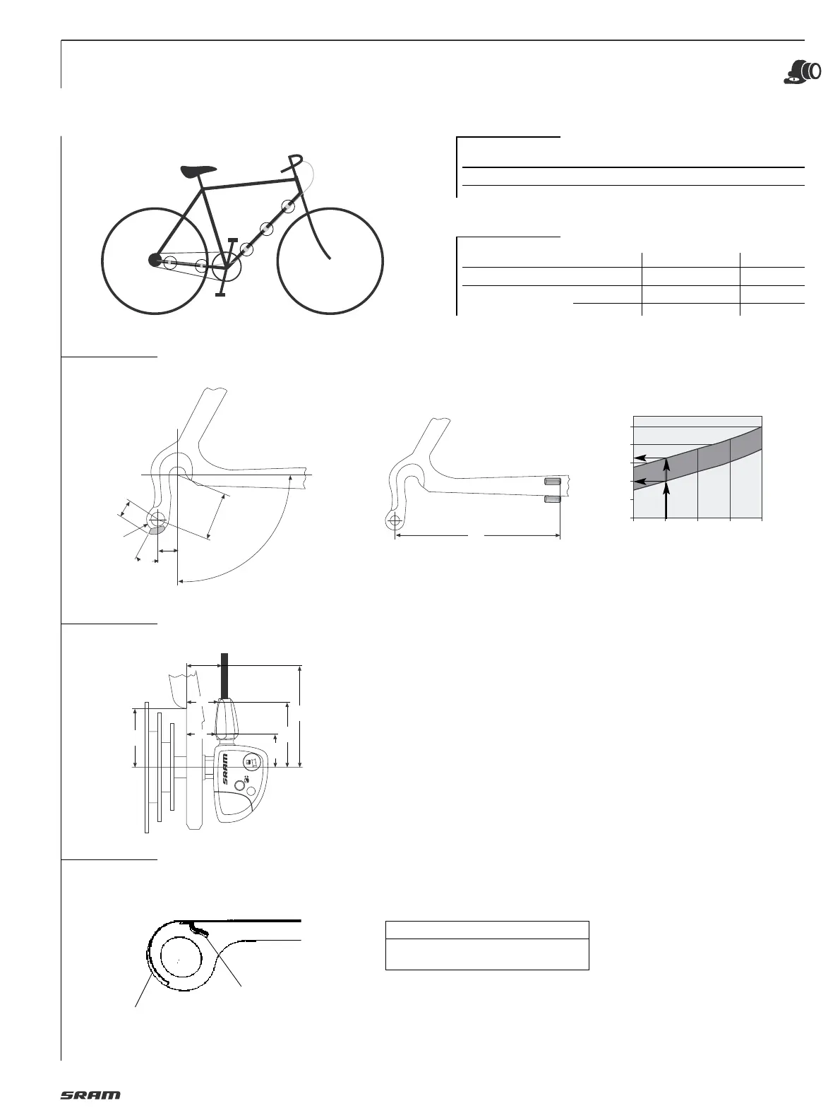
Cable routing
DualDrive 27 / DualDrive 24
Hub cable Along chainstay only
Derailleur cable Along chainstay only
Cable attachement
see Fig. 1
Cable housing Attachement points Cable stops
Hub Continuous 1 / 2 / 3 / 4 (see Fig. 1) —
Derailleur Continuous 1 / 2 / 3 / 4 / 5 (see Fig. 1) —
Open — 1/5 (Fig. 1)
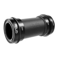
CABLE HOUSING FOR DERAILLEUR
1
2
3
4
5
Length X min. 90 mm.
Cable stop below or beside chainstay.
X (mm)
90 100 110 120 130
L (mm)
200
180
160
140
120
100
X
Rear cable stop position Rear housing length
Example: Distance X = 100 mm cable
housing length L = 140 – 165 mm.
➔
3
1
2
4
1
ø max. 220 mm
32
60
25
45
15
14
13
R2
R1
A
X
L
90°