6
DUALDRIVE
ASSEMBLY
Technical Manual 2006
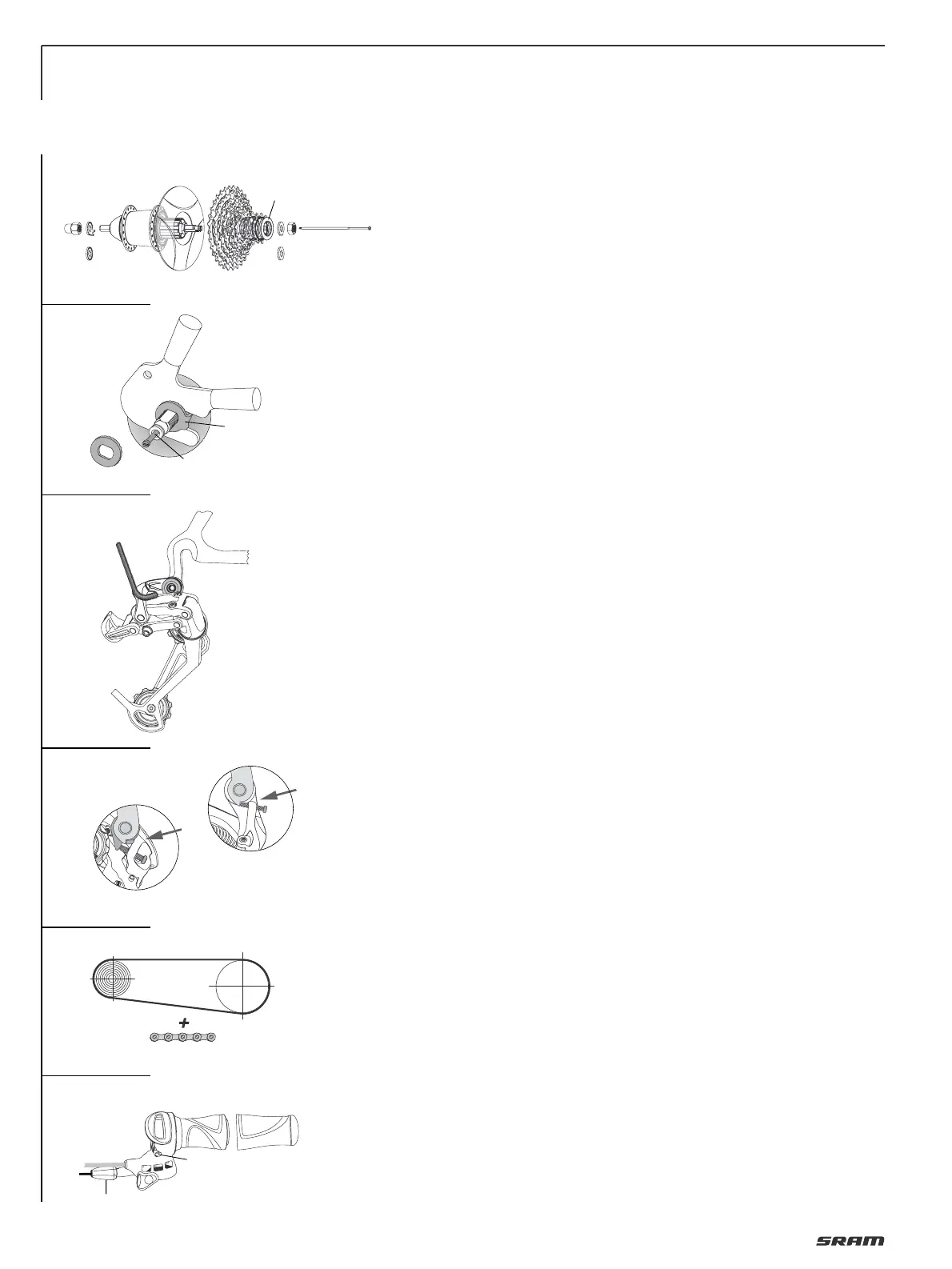
ASSEMBLY HUB
• Lace the wheel as normal.
• Place spoke protector disc (1, Fig. 1) on
shoulder of hub, fit cassette (2) onto
driver profile. Screw lock nut (3) with
cassette tool (Park Tool FR-5 or SRAM
Part No. 4624 411 010), tightening torque:
40 Nm (350 in.lbs.).
• Screw shifting rod (1, Fig. 2) into the hub
axle and tighten it with 0.2 Nm (1.8 in.lbs.).
• Fit wheel in dropouts.
• Place retaining washers (Fig. 2) on both
sides of the axle – the serrations must
bear against the dropout.
– Version for horizontal dropouts (2): the
lug must engage in the dropout slot.
– Version for vertical dropouts (3):
without lug.
• Tighten up axle nuts. Tightening
torque 30 – 40 Nm (266 – 350 in.lbs.).
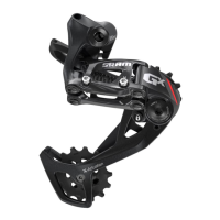
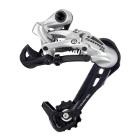
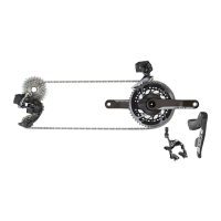
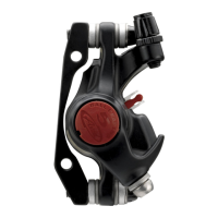
ASSEMBLY DERAILLEUR
Advice:
Check the rear derailleur hanger
alignment. A bent rear derailleur hanger
will result in inaccurate index shifting.
• Attach the rear derailleur to the frame’s
rear derailleur hanger using a 5 mm hex
head wrench (Fig. 3).
• Check that the b-adjust washer tab
(b-adjust screw at DualDrive 24) is clear
of the rear derailleur dropout tab (Fig. 4).
• Tighten the 5 mm hex hanger bolt to
8 – 10 Nm (70–85 in.lbs.).
CHAIN LENGTH
• Bypassing the rear derailleur, run the
chain around the largest cog/large
chainring combination (Fig. 5).
– For rear suspension frames, position
the rear suspension for the greatest
chain length required.
• Add 4 LINKS or 3 link + Connecting Link
to this length for proper chain length.
ASSEMBLY SHIFTER
Caution:
• Never use lubricants or solvents to
install handlebar grips. Handlebar grips
provide safety function.
For this reason, they should be
mounted in such a way as to make sure
they do not slip off handlebar!
• Always check the front and rear brake
levers for proper operation.
If there is interference between shifters
and brake levers, re-adjust lever and
shifter placement.
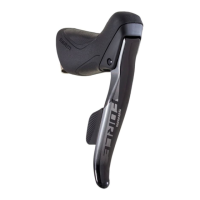
DualDrive single sided shifter:
• Slide the shifter (1, Fig. 6) onto the
handlebar.
• Rotate the shifter until the barrel
adjuster (4) is beneath (but out of the
way of) the brake lever.
• Tighten the 3 mm hex clamp bolt (2) to
1.9 – 2.5 Nm (17 – 22 in.lbs.).
• Slide the handlebar grip (3) onto the
handlebar.
DualDrive Trigger shifter (without picture):
• Slide shifter and brake lever onto hand-
lebar. Either component can be mounted
first, depending on personal preference.
• Slide the handlebar grip onto the
handlebar.
• Tighten the 5 mm hex clamp bolt to 5 Nm
(44 in.lbs.).
DualDrive Twist shifter (without picture):
• Slide the shifter onto the handlebar.
• Tighten the 3 mm hex clamp bolt to
1.9 Nm (17 in.lbs.).
• Slide the
plastic washer onto the hand-
lebar.
• Slide the stationary grip onto the hand-
lebar.
INSTALLING CLICKBOX
• Fit the cable and avoid small radius.
• Cable attachment points see Page 5 /
Fig. 1.
Cable housing must be movable inside
attachment.
• Place shift lever in uphill riding mode /
gear position „1“ (Fig. 7).
• Push Clickbox button down (Fig. 7).
• Push on Clickbox to the stop on the hub
axle.
• Press button up.
• Place thumb shift lever in standard
riding mode / gear position „2“ (Fig. 8).
• Match up the marks in the Clickbox
viewing window by twisting the
barrel adjuster (Fig. 8).
1
4
3
2
3
2
1
5
6
5 mm
8 – 10 Nm
70 – 85 in.lbs.
(4 Links)
DualDrive 24
DualDrive 27
2
4
1
3
1
0.2 Nm
1.8 in.lbs.
2
3