UM0289 Hardware
11/29
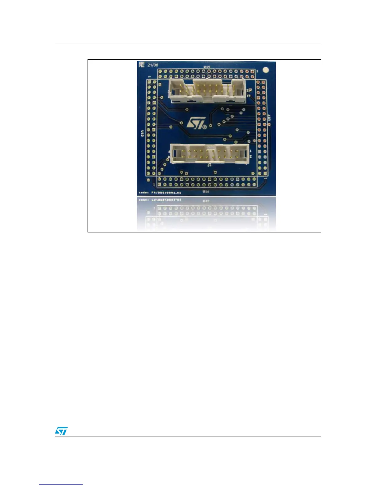
Figure 7. Feedback board - TOP
In order to report the feedback of motors, a 20-pin flat cable could be used. The first
connector can be used for an incremental encoder as the timer pins are used for
incremental interface mode. The second connector can be used for absolute encoder
feedback where the GPIO and capture pins are used.
Note: The system allows the feedback of encoder signals (A and B channels) for each motor,
Signals must be squared and with the right logic level (0 and 5V). When necessary, refer to
the datasheet of the encoder used. If needed, pull-up the encoder signals (not provided with
encoder kit).