UM0289 ST10 firmware
19/29
ACK timeout is fixed at 10 ms, both for the PC and ST10, and the payload of the "ACK"
frame is the command code to be acknowledged.
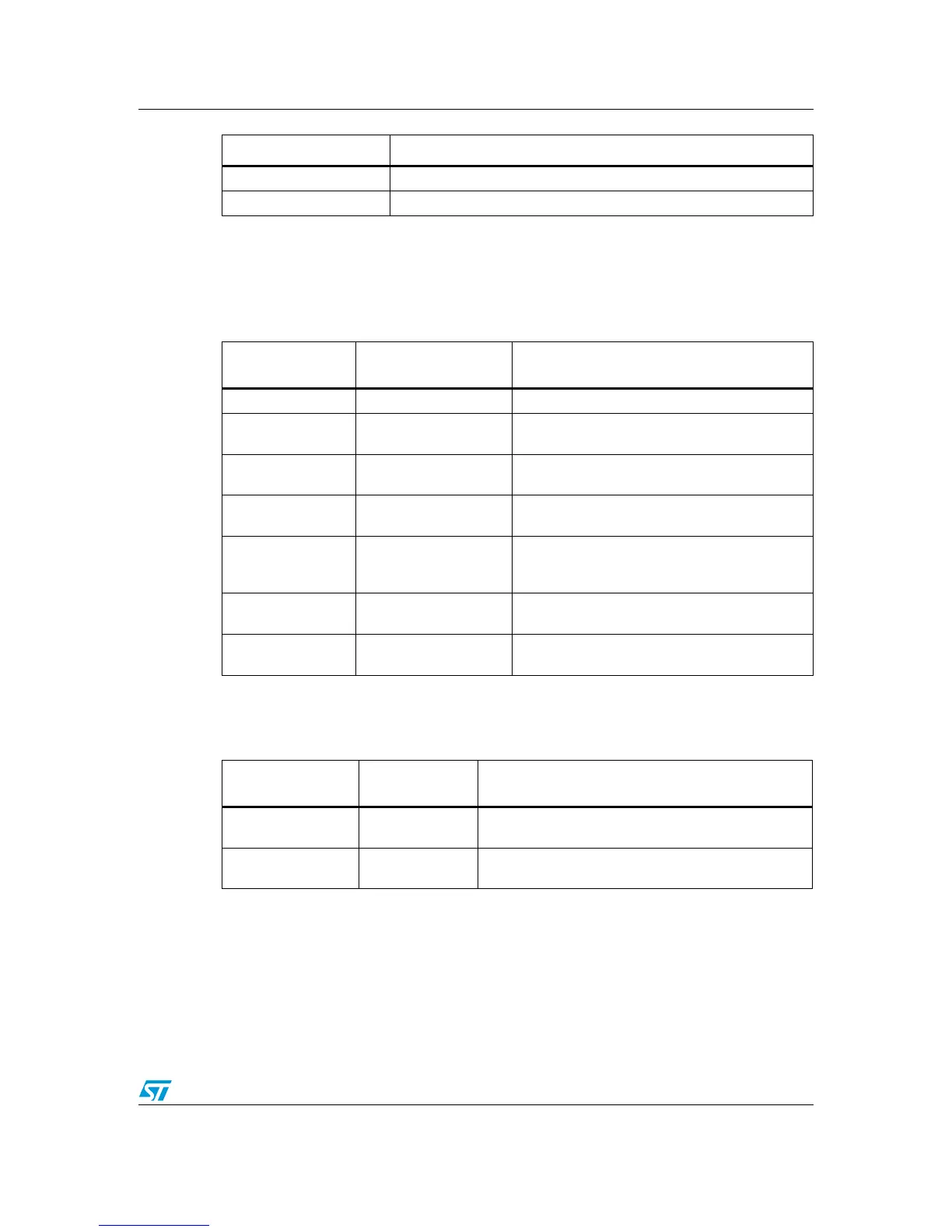
"Set_PID_Control" (0x09) is the frame used for setting the specific values of each control
loop, the contents of this frame is shown in the table below.
Table 6. Table 6 - Set_PID_Control payload
"Set_Control_Loop time" (0x0A) is a frame used to set the control loop time of each motor
control, according to the table below.
Table 7. Set_Control loop time payload
"Send_Parameters" (0x40) is a particular frame used to send the status of all system
parameters to the PC, the contents of this frame is shown in Ta b l e 8 .
0x3A Third connector with eval 6235
0x3B Third connector with eval 6205
Payload
byte order
Field Description
1 Motor Connector Association connector-powerSPIN board
2Driver
Byte for reserved use, indicating the kind of driver
(0xCD for a6205,0xEB for a 6235)
3-4 Encoder
2 Bytes indicating number of pulse for revolution of
motor encoder.
5-6 Speed
2 Bytes indicating the reference speed of motor
(range 1-3000 rpm)
7-8 P
2 Bytes indicating the proportional gain of the
speed control (range 1-1000, with a firmware
scaling)
9-10 I
2 Bytes indicating the integral gain of the speed
control (range 1-1000, with a firmware scaling)
11-12 D
2 Bytes indicating the derivative gain of the speed
control (range 1-1000, with a firmware scaling)
Payload
byte order
Field Description
1 Motor Connector
1 Byte indicating which powerSPIN board is connected
to a specific connector.
2Time
Byte indicating the control loop time (number of 200us
steps to be added to the basic control loop of 1ms).
Byte Value