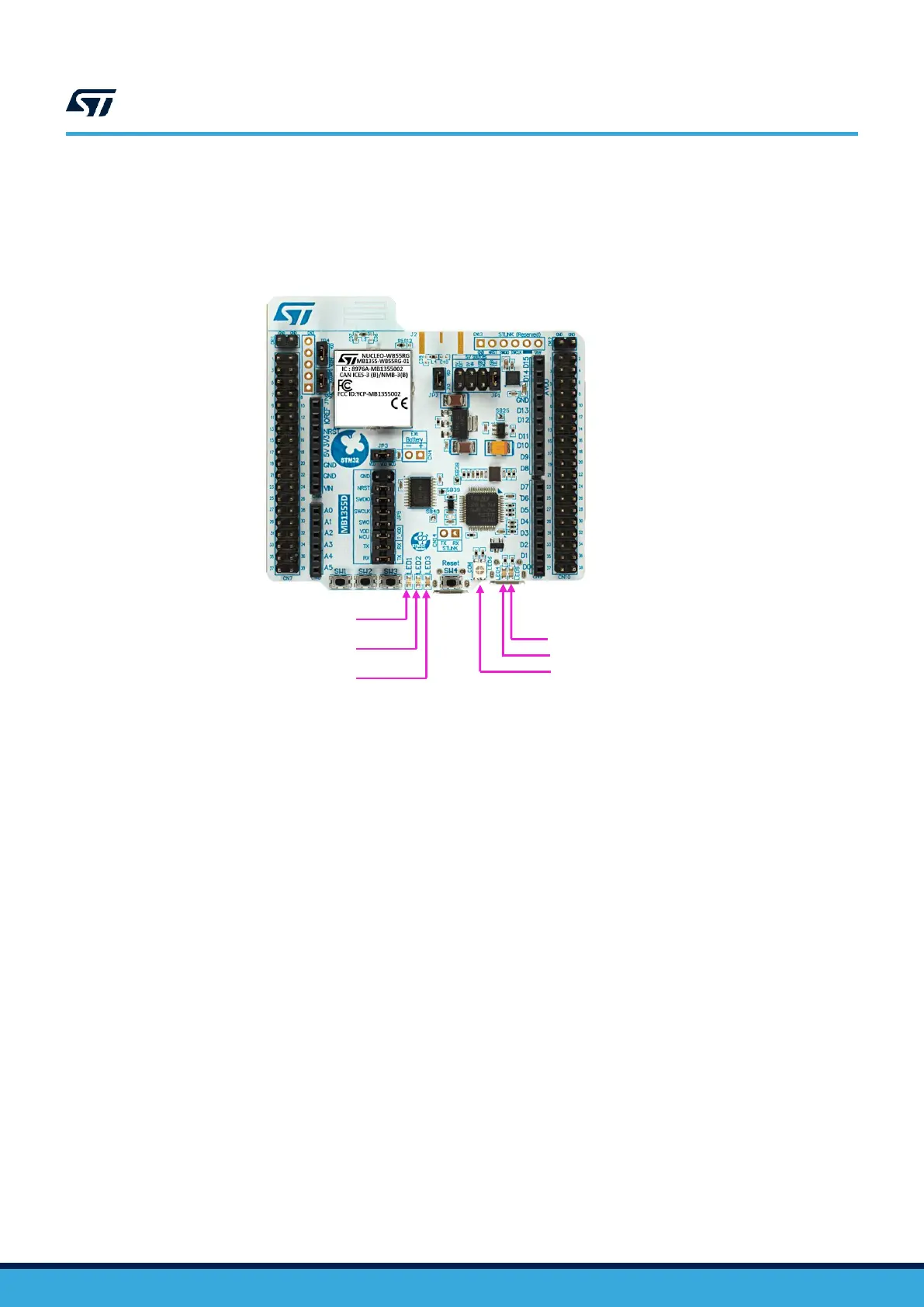
1. LD1: this blue LED is available for user application.
2. LD2: this green LED is available for user application.
3. LD3: this red LED is available for user application.
4. LD4: this LED turns red to indicate that the current distribution cannot be performed as expected when the
board is supplied by USB_STLINK.
5. LD5: this LED turns green when the 5V is available. To select the 5 V source, refer to Section 7.1.3 for
further details.
6. LD6 is a bi-color LED, which default status is red. It turns to green to indicate that communication is in
progress between the host PC and ST-LINK/V2-1 with the following steps:
– Slow blinking red and OFF: at power-on, before USB initialization
– Fast blinking red and OFF: after the first correct communication between the host PC and ST-LINK/
V2-1 (enumeration)
– Red ON: when initialization between the host PC and ST-LINK/V2-1 is successfully finished.
– Green ON: after successful target communication initialization
– Blinking red and green: during communication with the target
– Green ON: communication is successfully finished and OK.
– Orange ON: communication failure.

 Loading...