7.1 Power supply
7.1.1 General description
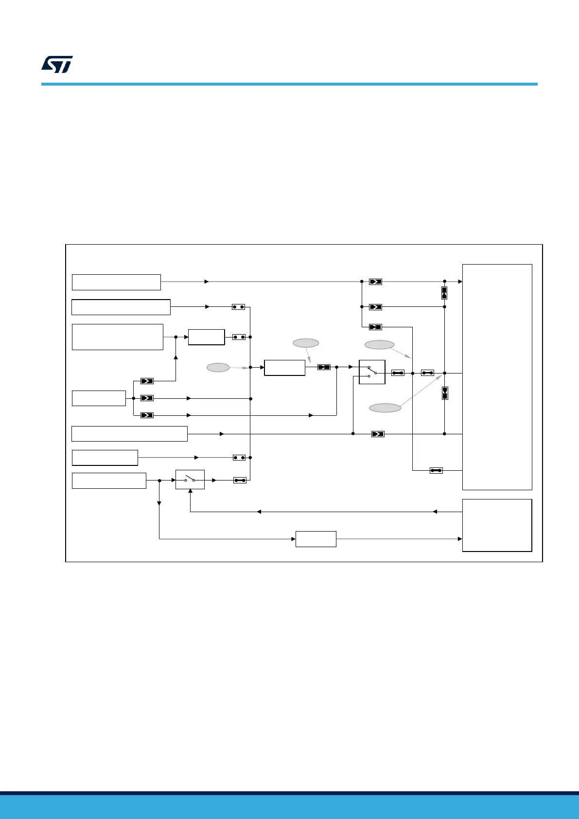
By default, the STM32WB55RG microcontroller embedded on this Nucleo board is supplied by 3V3 but the board
proposes a lot of possibilities to supply the device. The 3.3 V can first come from the ST-LINK USB, ARDUINO
®
,
or ST morpho connectors. Moreover, the STM32WB55RG can be supplied by an external source, between 1.8
and 3.3 V. Thanks to the level shifter, the debug by embedded ST-LINK is always possible even if the supply
voltage of the target is different from 3V3 (ST-LINK supply). Figure 7 shows the power tree. Moreover, this figure
also shows the default state of the jumpers and the solder bridges.
Figure 7. NUCLEO-WB55RG power tree
ST Restricted
USB STLNK (CN15)
Arduino VIN (CN6-8)
MORPHO VIN (CN7-24)
LDO 5V
STM32WB55RG
LDO 3V3
LDO 3V3
JP1(3-4)
JP1(7-8)
Open
Close
Close
VDD
VDDA/VREF+
VDDSMPS
Arduino AVDD (CN5-8)
SB14
SB13
SB17
SB16
Open
Open
Open
STM32F103
(STLINK MCU)
NUCLEO-WB15CC
Ext (CN4-1)
Close
JP2
JP1(1-2)
Open
VBAT
MORPHO 5V_EXT(CN7-6)
U2
Optional CR2032 Socket (CN2)
SB19
Open
Close
SB20
JP3
5V
3V3
VDD
SW5
U4
VDD_MCU
Close
Close
Open
Open
SB25
SB27
SB26
SB24
Close
JP6
Close
U3
U5
JP1(5-6)
USB MCU (CN1)
7.1.2 7 to 12 V power supply
NUCLEO-WB55RG can be powered with a 7 to 12 V DC power source. There are three accesses for this type of
DC levels:
1. VIN CN6 pin 8 of the ARDUINO
®
connector. It is possible to apply until +12 V on this pin or use an
ARDUINO
®
shield which can deliver this type of voltage on the VIN pin.
2. VIN CN7 pin 24 of the ST morpho connector. It is possible to apply until +12 V on this pin like for the
ARDUINO
®
connection.
3. CN4 external input. In this case, pay attention to the setting of the jumpers and solder bridges which is very
important. Refer to Table 4.
These sources are connected to the U2 linear low drop voltage regulator. The 5 V output of this regulator is a
potential source of 5V. Refer to Section 7.1.3 for further details.

 Loading...