List of figures
List of figures
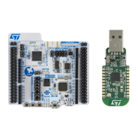
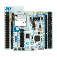
Figure 1. NUCLEO-WB55RG top view .................................................................................................................................................. 1
Figure 2. Hardware block diagram ......................................................................................................................................................... 8
Figure 3. NUCLEO-WB55RG PCB top side ......................................................................................................................................... 9
Figure 4. NUCLEO-WB55RG PCB with details of the main part (SoC and RF) .............................................................................. 9
Figure 5. NUCLEO-WB55RG PCB bottom side .................................................................................................................................10
Figure 6. NUCLEO-WB55RG mechanical dimensions (in millimeters) ...........................................................................................11
Figure 7. NUCLEO-WB55RG power tree ............................................................................................................................................12
Figure 8. Current measurement with an ammeter ............................................................................................................................. 14
Figure 9. Current measurement with an external power supply .......................................................................................................15
Figure 10. USB composite device .......................................................................................................................................................... 16
Figure 11. Interconnection bloc diagram between STM32WB55RG and ST-LINK/V2-1 ................................................................17
Figure 12. LEDs location ..........................................................................................................................................................................19
Figure 13. Push-buttons location ............................................................................................................................................................ 20
Figure 14. RF I/O stage ............................................................................................................................................................................ 21
Figure 15. SMPS part ...............................................................................................................................................................................22
Figure 16. ARDUINO
®
Uno connectors and ARDUINO
®
shield location ...........................................................................................23
Figure 17. ARDUINO
®
connector location and pinout .........................................................................................................................24
Figure 18. Pinout of ARDUINO
®
and ST morpho connectors ............................................................................................................ 26
 Loading...
