8/12
ST7 USB Low-Speed Evaluation Board
2.2.2 COMMUNICATION WITH THE EVALUATION BOARD
2.2.2.1 Controlling the evaluation board from a host PC
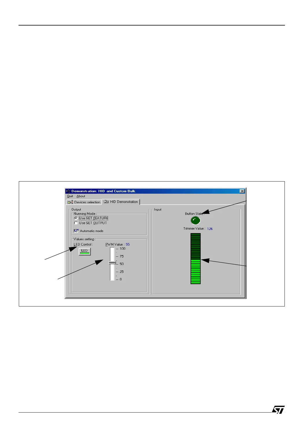
The HID demonstration tabsheet, shown in Figure 5, displays the following information:
Click on the ON/OFF button in the application dialog box to switch ON the LED LD2 on the
board. Click again to switch it OFF. The slider bar controls the brightness of a LED LD3
(ST72F62 or ST72F61) or LD1 (ST72F63B). Each slider bar value will be converted to a pulse
width modulation (PWM) signal by the microcontroller.
2.2.2.2 Displaying the evaluation board state
– Button State: This red LED changes its state when you press the SW1 push button on the
evaluation board.
– Trimmer Value: This value is the result of the Analog-to-Digital Conversion of the RV1 trim-
mer output. When you turn the trimmer on the evaluation board to a different position, the
new ADC value is transmitted via the USB bus and displayed on the progress bar of the
HID demonstrator.
Figure 5. HID Demonstrator window
2.3 REMOTE WAKE UP FUNCTION
The remote wake-up function is also supported by the evaluation board. By pressing SW3
(ST72F62 or ST72F61) or SW2 (ST72F63B) you can wake-up the PC from Stand-By mode.
Under Windows XP, the remote wake-up capability should be enabled. For that you should go
to the “Device Manager” then “Human Interface Device” and “HID-compliant device”. On the
tabsheet “Power Management”, select “Allow this device to bring the computer out of
standby”.
“LED Control”
Red LED
Slider Bar
Progress Bar
(LED brightness)
Button
 Loading...


