9/12
ST7 USB Low-Speed Evaluation Board
2.4 ADDING CIRCUITRY ON THE WIRE-WRAP AREA
The evaluation board features a 43-hole row with all the microcontroller pins plus one side of
the analog trimmer. These connection points can be used for signal probing or rewiring to the
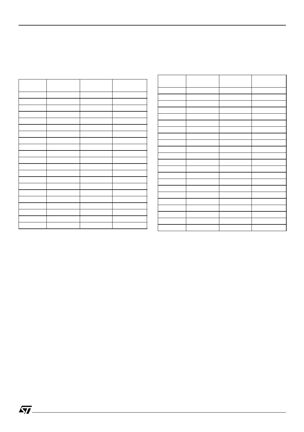
wire-wrap area. The table below gives the definition of these points for each MCU used.
– USB LOW-SPEED Evaluation Board Di-
agram
Probing
Point
ST72F62 ST72F61 ST72F63B
1PD6
2PD5
3PD4
4PD3
5PD2
6V
PP
V
PP
V
PP
7PD1
8PD0
9PC7
10 PC6
11 PC5
12 PC4
13 PC3
14 PC2 PC2
15 OSCIN OSCIN OSCIN
16 OSCOUT OSCOUT OSCOUT
17 V
SS
V
SS
V
SS
18 V
DD
V
DD
V
DD
19 PC1 PC1
20 PC0 PC0
21 PB7 PB7 PB7
Probing
Point
ST72F62 ST72F61 ST72F63B
22 PB6 PB6 PB6
23 PB5 PB5 PB5
24 PB4 PB4 PB4
25 PB3 PB3 PB3
26 PB2 PB2 PB2
27 PB1 PB1 PB1
28 PB0 PB0 PB0
29 PA7 PA7
30 PA6 PA6
31 PA5 PA5
32 PA4 PA4
33 PA3 PA3
34 PA2 PA2 PA2
35 PA1 PA1 PA1
36 PA0 PA0 PA0
37 RESET RESET RESET
38 V
SSA
39 USBDM USBDM USBDM
40 USBDP USBDP USBDP
41 USBVCC USBVCC USBVCC
42 V
DDA
V
DDA
43 An.Trim. An.Trim. An.Trim.
 Loading...


