5/12
ST7 USB Low-Speed Evaluation Board
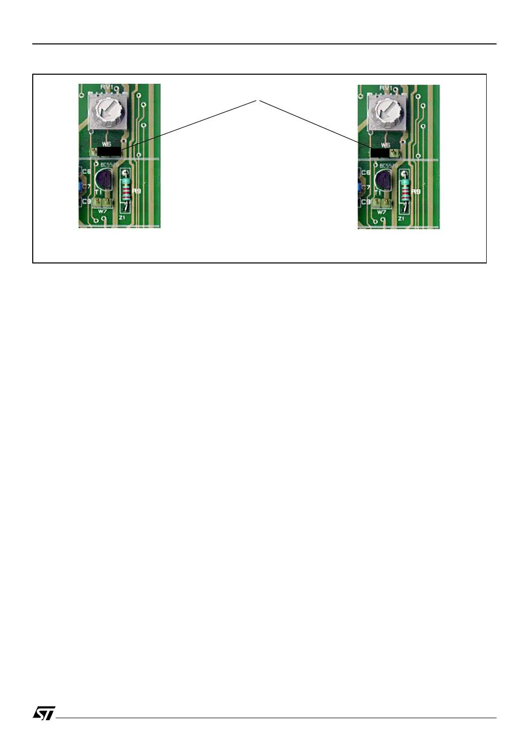
Figure 2. Device selection for A/D conversion
If you are using the analog trimmer, select the installed ST7 device using jumper W6 as shown
in Figure 2. This ties the analog trimmer to the PA0 I/O port of the ST72F62 and to the PB0
port of the ST72F63B. Any other analog input pin on the microcontroller can be used by re-
moving the W6 jumper and wiring the center pin of W6 to the analog input.
The W7 jumper can be used to connect or disconnect an external 12V charge pump in case
you want to program the Flash.
1.4.3 Device Selection
■
Three devices can be used with this board:
– ST72F63B devices in SDIP32 package on the internal socket
– ST72F62 devices in SDIP42 package on the external socket
– ST72F61 devices in DIP20 by using a user-supplied SDIP42-DIP20 adaptor (Figure 7).
ST72F62
ST72F63B
W6 JUMPER