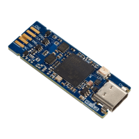
6 Board connectors
6.1 Connectors
Per convention, refer to Table 2 for I/O type definition:
Table 2. I/O type definition
Type Definition
S Supply pin
I Input‑only pin
O Output‑only pin
I/O Input and output pin
6.2 Pads on board to CN2 BTB card edge connector
The pads on the board have the same function as the STDC14 connector. The user can select a BTB card edge
connector to connect STLINK-V3MINIE and the target board. The board‑to‑board card edge connector reference
is 009159010061911 from AVX.
Table 3. Pads on board to CN2 BTB card edge connector
Side Pin number Pin description Type
TOP
1
Reserved
(1)
-
2
T_JTDI/NC
(2)
O
3 T_JTMS/T_SWDIO I/O
4 T_JCLK/T_SWCLK O
5
T_JTDO/T_SWO
(3)
I
BOTTOM
6 GND S
7 T_VCP_RX O
8 T_VCP_TX I
9 T_NRST O
10 T_VCC I
1. Do not connect on target.
2. NC means not required for SWD (Serial Wire Debug) connection.
3. SWO (Serial Wire Output) is optional, and only required for SWV (Serial Wire Viewer) trace.
UM2910
Board connectors
UM2910 - Rev 2
page 10/20

 Loading...