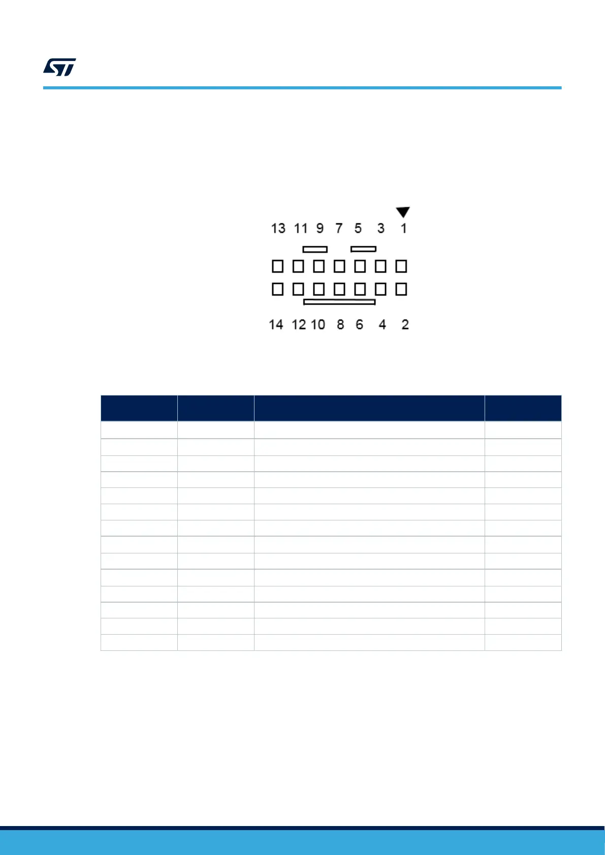
6.3 CN4 STDC14 connector
The CN4 STDC14 connector allows the connection to an STM32 target using the JTAG or SWD protocol,
respecting from pin 3 to pin 12 the MIPI‑10 (Arm
®
Cortex
®
debugging connector) pinout. It also advantageously
provides two UART signals for the Virtual COM port. The related pinout for the STDC14 connector is listed in
Table 4.
Figure 6. CN4 STDC14 connector (Top view)
Table 4. CN4 STDC14 connector pinout
STDC14 pin
number
MIPI‑10 pin
number
Pin description Type
1 -
Reserved
(1)
-
2 -
Reserved
(1)
-
3 1 T_VCC I
4 2 T_JTMS/T_SWDIO I/O
5 3 GND S
6 4 T_JCLK/T_SWCLK O
7 5 GND S
8 6
T_JTDO/T_SWO
(2)
I
9 7 T_JRCLK I
10 8
T_JTDI/NC
(3)
O
11 9 GNDDETECT O
12 10 T_NRST O
13 - T_VCP_RX O
14 - T_VCP_TX I
1. Do not connect on target.
2. SWO is optional, required only for Serial Wire Viewer (SWV) trace.
3. NC means not required for SWD connection.
UM2910
CN4 STDC14 connector
UM2910 - Rev 2
page 11/20
 Loading...